A heating element detection system, method, device and storage medium

A heating element and detection system technology, applied in the direction of test/monitoring control system, general control system, control/regulation system, etc., can solve the problems of affecting production progress, inaccurate detection and judgment of heating element failure, frequent operation, etc., to achieve Guaranteed production progress, realized automatic fault detection, and improved detection efficiency

Active Publication Date: 2022-03-29
GUANGDONG HENGTONG PHOTOELECTRIC SCI & TECH +1
View PDF29 Cites 0 Cited by
  • Summary
  • Abstract
  • Description
  • Claims
  • Application Information

AI Technical Summary

Problems solved by technology

[0004] The existing heating element fault detection methods mainly include two types, one is the resistance detection method, which uses a multimeter and other equipment to detect the resistance value of the heating element, and then compares it with the theoretically calculated value, but only when the heating stops and the line is disconnected The other is the current detection method, which uses a clamp meter to detect the current of the heating line, and then compares it with the theoretical calculation value, but it is not practical in the PID temperature control system , because the on-off operation of the PID temperature control system is too frequent, the instantaneous current of the heating element will be too large. At this time, the fault detection and judgment of the heating element is not accurate. At the same time, the workload is heavy, and the effect of automatic detection cannot be achieved.

Method used


Image

  • A heating element detection system, method, device and storage medium
  • A heating element detection system, method, device and storage medium
  • A heating element detection system, method, device and storage medium

Examples


Embodiment 1

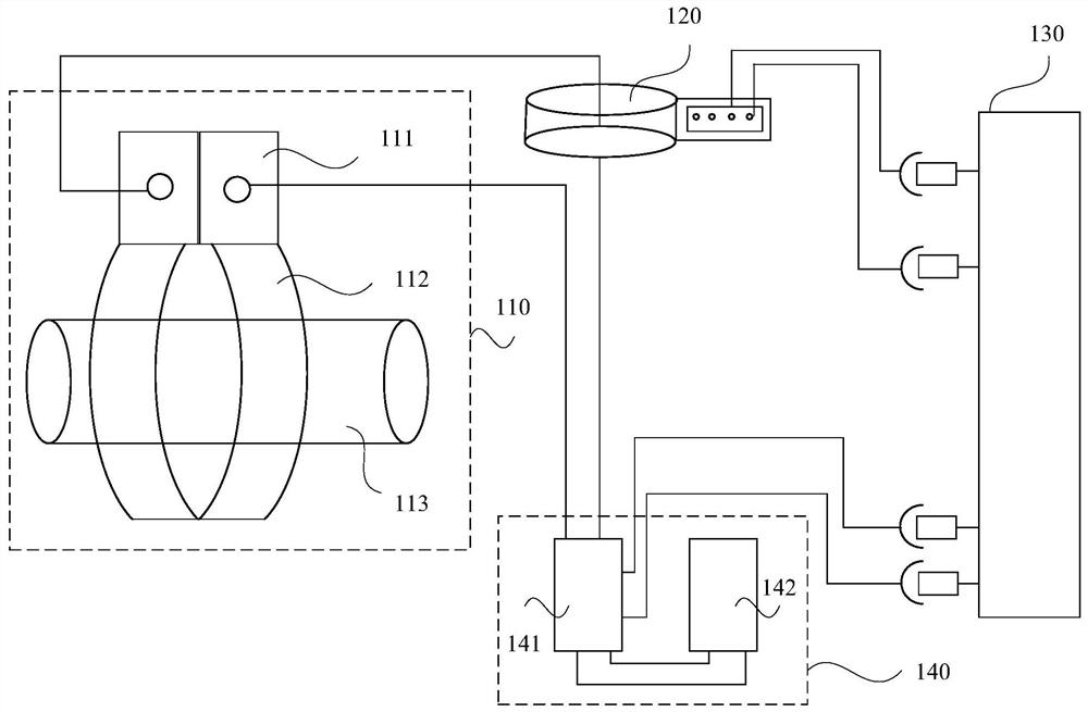
[0040] figure 1 It is a schematic structural diagram of a heating element detection system provided in Embodiment 1 of the present invention. This embodiment is applicable to the automatic detection of heating element failures based on PID control. The specific structure of the heating element detection system includes:

[0041] Element heating module 110, current transformer 120, PLC control module 130 and heating power supply control module 140; said element heating module 110 is electrically connected with said current transformer 120 and said heating power supply control module 130 respectively, and said PLC controls The module 130 is electrically connected to the current transformer 120 and the heating power control module 140 respectively;

[0042] The heating power supply control module 140 is configured to provide power to the element heating module 110 according to the received heating start signal output by the PLC control module 130 after the PLC control module 130 ...

Embodiment 2

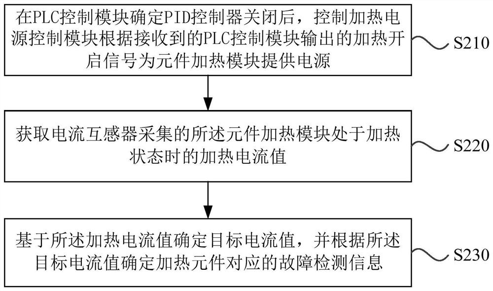
[0071] figure 2 It is a schematic flowchart of a heating element detection method provided in Embodiment 2 of the present invention. This embodiment is applicable to the situation of automatic detection of heating element failure based on PID control.

[0072] Correspondingly, the method in this embodiment specifically includes:

[0073] S210. After the PLC control module determines that the PID controller is off, control the heating power supply control module to provide power to the element heating module according to the received heating start signal output by the PLC control module.

[0074] On the basis of the above-described embodiments, after the PLC control module determines that the PID controller is closed, the control heating power supply control module provides power for the element heating module according to the received heating start signal output by the PLC control module, including: determining in the PLC control module After the PID controller closes the p...

Embodiment 3

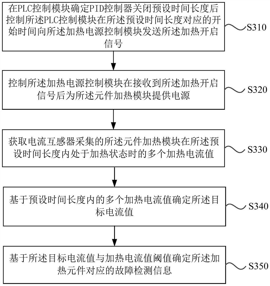
[0088] image 3 It is a schematic flowchart of a heating element detection method provided by Embodiment 3 of the present invention. The technical solutions of the embodiments of the present invention are further optimized on the basis of the above embodiments. The method of this embodiment specifically includes:

[0089] S310. After the PLC control module determines that the PID controller is turned off for a preset time length, control the PLC control module to send the heating start signal to the heating power supply control module at a start time corresponding to the preset time length.

[0090] S320. Control the heating power supply control module to provide power to the element heating module after receiving the heating start signal.

[0091] S330. Obtain a plurality of heating current values ​​collected by the current transformer when the element heating module is in a heating state within the preset time length.

[0092] S340. Determine the target current value base...


PUM


Abstract

The embodiment of the invention discloses a heating element detection system, method, device and storage medium. The heating element detection system includes an element heating module, a current transformer, a PLC control module and a heating power supply control module; the element heating module is electrically connected with the current transformer and the heating power supply control module respectively, and the PLC control module is respectively connected with the current transformer and the heating power supply The control module is electrically connected; the heating power control module is used to provide power for the element heating module according to the received heating start signal output by the PLC control module after the PLC control module determines that the PID controller is closed; the current transformer is used to collect the element The heating current value when the heating module is in the heating state; the PLC control module is used to determine the target current value based on the heating current value, and determine the fault detection information corresponding to the heating element according to the target current value. The technical solution of the embodiment of the present invention is to realize the automatic detection of heating element faults, improve the detection efficiency, and ensure the production progress.

Description

technical field [0001] The embodiments of the present invention relate to the technical field of temperature control, and in particular to a heating element detection system, method, device and storage medium. Background technique [0002] Extrusion equipment is required in the production and manufacture of optical cables and cables. When half of the heating elements of the extrusion equipment fail, the extruded plastic in that part of the heating element failure will not be completely melted, which will cause the product to fall off or even directly scrapped. At the same time, repeated occurrence of non-melting material will also cause certain damage to the screw, screw boring and mold of the extrusion equipment, and increase the cost input. [0003] Whether the failure of heating elements can be detected in time directly determines the quality of the product. There are a large number of heating elements in each production line and failures may occur every minute. It is al...

Claims


Application Information

Patent Timeline
Patent Type & Authority Patents(China)
IPC IPC(8): G05B23/02
CPCG05B23/0213G05B2219/24065
Inventor 罗志孝王大炜陆永志
Owner GUANGDONG HENGTONG PHOTOELECTRIC SCI & TECH
Why Eureka
Try Eureka