Flight pixel filtering method and system

A filtering and pixel technology, applied in the field of computer vision, which can solve the problems of mistaken deletion of surface points, inaccurate screening of flying pixels, insufficient plane jitter optimization of point cloud data, etc.

Pending Publication Date: 2020-10-27
HANGZHOU GUANGPO INTELLIGENT TECH CO LTD
View PDF8 Cites 2 Cited by
  • Summary
  • Abstract
  • Description
  • Claims
  • Application Information

AI Technical Summary

Problems solved by technology

This technical solution has the technical problem of inaccurate screening of flying pixels
The patent application number is 2012800309601, which improves the quality of depth measurement, and discloses a method for correcting the depth value of defects in the de

Method used


Image

  • Flight pixel filtering method and system
  • Flight pixel filtering method and system
  • Flight pixel filtering method and system

Examples


Embodiment Construction

[0040] The present invention will be described in detail below in conjunction with the specific embodiments shown in the accompanying drawings, but these embodiments do not limit the present invention, those skilled in the art make structural, method, or functional changes based on these embodiments All are included in the scope of protection of the present invention.

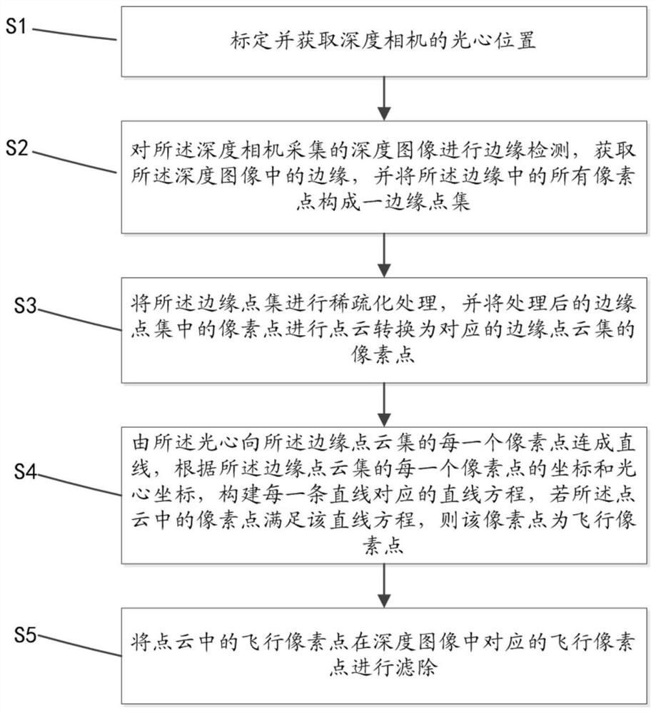
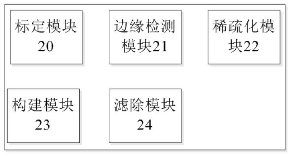
[0041] Such as figure 1 As shown in an embodiment of the present invention, the present invention provides a flying pixel filtering method, the method comprising:

[0042] S1. Calibrate and obtain the optical center position of the depth camera;

[0043] S2. Perform edge detection on the depth image collected by the depth camera, acquire edges in the depth image, and form all pixels in the edge into an edge point set;

[0044] S3. Thinning the edge point set, and converting the pixels in the processed edge point set into a point cloud into corresponding pixel points in the edge point cloud;
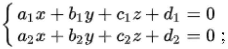
[0045] S4, form...


PUM


Abstract

The invention discloses a flight pixel filtering method. The method comprises the steps of calibrating and obtaining the optical center position of a depth camera; carrying out edge detection on the collected depth image to obtain an edge in the depth image, and forming an edge point set by all pixel points in the edge; carrying out sparse processing on the edge point set, and carrying out point cloud conversion on pixel points in the processed edge point set to obtain pixel points of a corresponding edge point cloud set; connecting each pixel point of the point cloud set from the optical center to the edge point cloud set into a straight line, constructing a straight line equation corresponding to each straight line according to the coordinate of each pixel point of the edge point cloud set and the optical center coordinate, and if the pixel point in the point cloud meets the straight line equation, determining the pixel point as a flight pixel point; and filtering out the flight pixel points corresponding to the flight pixel points in the point cloud in the depth image. Correspondingly, the invention also discloses a flight pixel filtering system. According to the invention, theflight pixels can be screened and deleted more accurately.

Description

technical field [0001] The invention relates to the technical field of computer vision, in particular to a method and system for filtering out flying pixels. Background technique [0002] The main reason for the generation of flying pixels is that each pixel on the TOF sensor has a certain physical size. When measuring the edge of an object, a single pixel will receive the light reflected from the foreground and the background at the same time, and the energy generated by the two is superimposed. The raw data acquired by the sensor contains multiple distance information. The obstacle recognition method whose patent application number is CN2019111710204, which announced the technical solution of flying pixel filtering, the solution is: traverse each pixel of the depth image, take each traversed pixel as the center pixel, traverse The depth value of each point in the area centered on this point is compared with this point. If the difference is greater than a threshold, the po...

Claims


Application Information

Patent Timeline
IPC IPC(8): G06T7/13G06T7/70G06T5/30
CPCG06T7/13G06T7/70G06T5/30G06T2207/10028
Inventor 黄泽仕徐勇军余小欢陈嵩白云峰
Owner HANGZHOU GUANGPO INTELLIGENT TECH CO LTD
Why Eureka
Try Eureka