Magnetic driving mechanism and electrical switch with same

A magnetic drive, electrical switch technology, applied in the direction of protection switch operation/release mechanism, etc., can solve the problems of slow action response speed of magnetic release, longer fault current existence time, insufficient armature action, etc., to improve the breaking fault. Circuit capability and reliability, improving mechanical transmission efficiency, and reducing the effect of mechanism response time

Pending Publication Date: 2020-10-27
XIAMEN HONGFA ELECTRICAL SAFETY & CONTROLS CO LTD
View PDF0 Cites 0 Cited by
  • Summary
  • Abstract
  • Description
  • Claims
  • Application Information

AI Technical Summary

Problems solved by technology

[0003] However, this kind of magnetic release has certain defects. When a short-circuit current occurs in the circuit, the yoke of the magnetic release needs to be magnetized for a certain period of time to generate magnetic force, then attract the armature to move, and finally release the lock by striking the lock mechanism. The buckle makes the switch cut off the fault current, which not only needs to go through two stages of mechanical transmission, but also the distance between the armature and the yoke of the magnetic tripper in the conventional technology is far away (the air gap between the armature and the yoke is large), resulting in the yoke to the armature The initial suction force is relatively small, and the action of the armature is not fast enough, so the response speed of the magnetic tripper is relatively slow, resulting in a longer time for the fault current to exist, which affects the safety of the system
In addition, magnetic releases usually have many parts and complex structures.

Method used


Image

  • Magnetic driving mechanism and electrical switch with same
  • Magnetic driving mechanism and electrical switch with same
  • Magnetic driving mechanism and electrical switch with same

Examples


Embodiment Construction

[0025] To further illustrate the various embodiments, the present invention is provided with accompanying drawings. These drawings are a part of the disclosure of the present invention, which are mainly used to illustrate the embodiments, and can be combined with related descriptions in the specification to explain the operating principles of the embodiments. With reference to these contents, those skilled in the art should understand other possible implementations and advantages of the present invention. Components in the figures are not drawn to scale, and similar component symbols are generally used to denote similar components.

[0026] The present invention will be further described in conjunction with the accompanying drawings and specific embodiments.

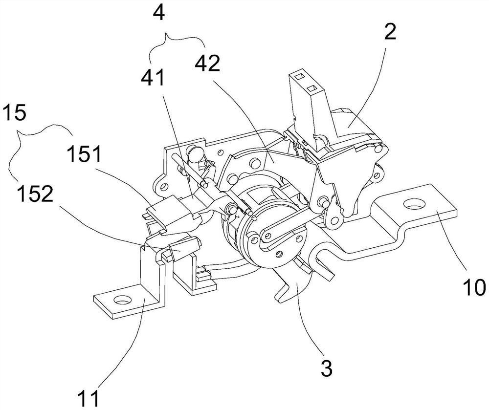
[0027] refer to figure 1 As shown, as a preferred embodiment of the present invention, a circuit breaker is provided, including a housing (not fully shown), an operating mechanism 2 installed on the housing, a contact ...


PUM


Abstract

The invention relates to a magnetic driving mechanism, which comprises an armature and a magnet yoke opposite to the armature, wherein the magnet yoke is installed at the position of a conductor to bedetected in an associated manner so as to constrain an electromagnetic field of the conductor in a centralized manner; the armature is in coupling connection with an actuating part of an electrical mechanism which needs to realize a function through displacement so as to be used for drive the actuating part by self displacement after the armature is magnetically adsorbed by the magnet yoke; and the magnet yoke is provided with a first extending part extending towards the armature, the armature is provided with a second extending part extending towards the magnet yoke, and the magnet yoke andthe armature are close to each other and are staggered with each other through the first extending part and the second extending part. The invention further relates to an electrical switch which is provided with the magnetic driving mechanism. Through the design of the mutual extending parts which are magnetically attracted, the air gap between the armature and the magnet yoke at the initial position is reduced, and the initial attraction force is improved.

Description

technical field [0001] The invention relates to a magnetic drive mechanism and an electric switch with the mechanism, and more particularly relates to the structural improvement of the armature and the yoke. Background technique [0002] The circuit breaker is a switching device widely used in the power distribution system. When the circuit is overloaded, short-circuited, or under-voltage, the circuit breaker needs to be able to quickly cut off the circuit to avoid burning the components under excessive current, so usually The circuit breaker has a quick trip mechanism to quickly break the circuit, and the speed of tripping and tripping directly affects the ability of the circuit breaker to cut off the fault current. The thermal magnetic release is a commonly used tripping mechanism in the field of circuit breakers. It is used to convert the received magnetic excitation and / or thermal deformation into the driving force to drive the tripping of the circuit breaker locking mec...

Claims


Application Information

Patent Timeline
Patent Type & Authority Applications(China)
IPC IPC(8): H01H71/68H01H71/10
CPCH01H71/10H01H71/68
Inventor 林新德黄蔚偈王应波林耀国卓江海张金泉
Owner XIAMEN HONGFA ELECTRICAL SAFETY & CONTROLS CO LTD
Why Eureka
Try Eureka