
Wireless charging transmitting module, wireless charging transmitting system and low-frequency signal transmission method

A wireless charging and transmitting module technology, applied in the direction of collectors, electric vehicles, electrical components, etc., can solve the problems of long open time, long open time, and inability to control the coil current of the power full bridge, and achieve flexible control and realization. The effect of low frequency signal transmission

Active Publication Date: 2020-10-27
CHENGDU YICHONG WIRELESS POWER TECH CO LTD
View PDF9 Cites 2 Cited by
  • Summary
  • Abstract
  • Description
  • Claims
  • Application Information

AI Technical Summary

Problems solved by technology

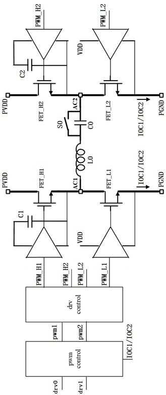
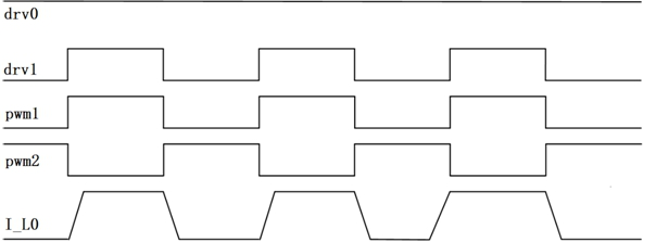
However, in this wireless charging system, the frequency of pwm1 is 500Hz to 10kHz. Because the power full bridge is on for a long time, the current flowing through the coil L0 is only determined by the DC resistance of the coil L0 and the switch S0, and the coil current cannot be realized. flexible control
Another problem is that because the FET_H1 and FET_H2 in the power full bridge are turned on for a long time (500Hz to 10kHz corresponds to 1mS to 50uS), so the BST capacitors C1 and C2 need to support the corresponding time, which limits the control circuit (full bridge PWM controller , full-bridge drive controller, 4 follower drivers) and the application range of capacitors C1 and C2

Method used


Image

  • Wireless charging transmitting module, wireless charging transmitting system and low-frequency signal transmission method
  • Wireless charging transmitting module, wireless charging transmitting system and low-frequency signal transmission method
  • Wireless charging transmitting module, wireless charging transmitting system and low-frequency signal transmission method

Examples


Embodiment Construction

[0029] In order to make the object, technical solution and advantages of the present invention clearer, the present invention will be further described in detail below in conjunction with the accompanying drawings and embodiments. It should be understood that the specific embodiments described here are only used to explain the present invention, and are not intended to limit the present invention, that is, the described embodiments are only some of the embodiments of the present invention, but not all of the embodiments. The components of the embodiments of the invention generally described and illustrated in the figures herein may be arranged and designed in a variety of different configurations. Accordingly, the following detailed description of the embodiments of the invention provided in the accompanying drawings is not intended to limit the scope of the claimed invention, but merely represents selected embodiments of the invention. Based on the embodiments of the present ...


PUM


Abstract

The invention discloses a wireless charging transmitting module, a wireless charging transmitting system and a low-frequency signal transmission method. The low-frequency signal transmission method comprises the following steps: S1, generating a low-frequency coil current signal by using a high-frequency full-bridge PWM controller; and S2, setting a current threshold value, and enabling the full-bridge PWM controller to perform reverse control when the coil current exceeds the current threshold value. According to the wireless charging transmitting module, the coil current can be flexibly controlled, and the application range of a control circuit and a capacitor in the wireless charging transmitting module is not limited, so that the required low-frequency signal transmission is realized.

Description

technical field [0001] The invention relates to the technical field of wireless charging and transmitting modules, in particular to a wireless charging and transmitting module, a system and a low-frequency signal transmission method. Background technique [0002] In the wireless charging system, the wireless charging transmitter module (TX) generates a 100kHz-200kHz coil current signal through the full bridge control. The coil current signal is coupled to the wireless charging receiving module (RX) through the coil, so as to realize the purpose of energy transmission and signal transmission from the wireless charging transmitting module (TX) to the wireless charging receiving module (RX). in some such as figure 1 In the application shown, through the control of switch S0, to achieve as figure 2 For the low frequency (500Hz~10kHz) coil current signal shown, the magnitude of this coil current signal must be flexibly controlled to suit different wireless charging transmitter...

Claims


Application Information

Patent Timeline
IPC IPC(8): H02J50/10H02J7/00H02M1/32
CPCH02J7/0029H02M1/32H02J50/10H02J7/00714
Inventor 戴义红
Owner CHENGDU YICHONG WIRELESS POWER TECH CO LTD
Learn More