Vapor chamber and processing method of vapor chamber

A processing method and vapor chamber technology, applied in the field of heat conduction, can solve the problems that copper foil or graphite heat dissipation methods cannot meet the heat dissipation requirements, and the heat dissipation effect cannot meet expectations, etc.

Active Publication Date: 2020-10-27
AAC TECH NANJING
View PDF5 Cites 10 Cited by
  • Summary
  • Abstract
  • Description
  • Claims
  • Application Information

AI Technical Summary

Problems solved by technology

[0002] Electronic devices in related technologies usually use copper foil or graphite for heat dissipation, but as some electronic devices become more powerful, they require higher heat dissipation performance, and copper foil or graphite heat dissipation methods gradually cannot meet the heat dissipation requirements.
[0003] In order to solve the above problems, some vapor chambers are used in the related art to dissipate heat. However, due to the structural shortcomings of the vapor chambers in the related art, the heat dissipation effect cannot meet expectations.

Method used


Image

  • Vapor chamber and processing method of vapor chamber
  • Vapor chamber and processing method of vapor chamber
  • Vapor chamber and processing method of vapor chamber

Examples


Embodiment Construction

[0037] To further illustrate the various embodiments, the present invention is provided with accompanying drawings. These drawings are a part of the disclosure of the present invention, which are mainly used to illustrate the embodiments, and can be combined with related descriptions in the specification to explain the operating principles of the embodiments. With reference to these contents, those skilled in the art should understand other possible implementations and advantages of the present invention. Components in the figures are not drawn to scale, and similar component symbols are generally used to denote similar components.

[0038] The present invention will be further described below in conjunction with the accompanying drawings and embodiments.

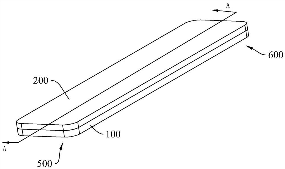
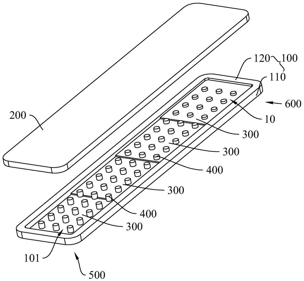
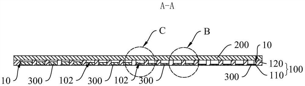
[0039] Please refer to figure 1 - Image 6 , an embodiment of the present invention provides a vapor chamber. The vapor chamber in this embodiment has a closed cavity 10 filled with a working fluid. The working fluid is ...


PUM


Abstract

The invention provides a vapor chamber and a processing method of the vapor chamber. The vapor chamber comprises a hot end close to a heat source and a cold end which is opposite to the hot end and far away from the heat source. The vapor chamber comprises a first cover plate and a second cover plate which is arranged opposite to the first cover plate and covers the first cover plate, wherein theside, which is close to the second cover plate, of the first cover plate is sunken away from the second cover plate to form a first groove, and the first cover plate and the second cover plate definea closed inner cavity filled with working liquid; the first cover plate comprises a bottom wall and a side wall, the bottom wall is opposite to the second cover plate and arranged at an interval, theside wall bends and extends towards the second cover plate from the periphery of the bottom wall and abuts against the second cover plate. The vapor chamber further comprises a capillary structure arranged on the bottom wall, wherein the thickness of the capillary structure is gradually increased in the direction from the hot end to the cold end. In the direction from the hot end to the cold end,the thickness of the capillary structure is gradually increased, the working liquid can flow to the hot end from the cold end more easily, the circulation speed of the working liquid from the liquid state to the gaseous state and then to the liquid state is higher, and the heat dissipation performance is better.

Description

【Technical field】 [0001] The invention relates to the technical field of heat conduction, in particular to a uniform temperature plate and a processing method for the uniform temperature plate. 【Background technique】 [0002] Electronic devices in related technologies usually use copper foil or graphite for heat dissipation. However, as some electronic devices become more powerful, they require higher heat dissipation performance, and copper foil or graphite heat dissipation methods gradually cannot meet the heat dissipation requirements. [0003] In order to solve the above problems, some vapor chambers are used in the related art to dissipate heat. However, due to certain structural shortcomings of the vapor chambers in the related art, the heat dissipation effect cannot meet expectations. [0004] Therefore, it is necessary to provide a novel vapor chamber to solve the above problems. 【Content of invention】 [0005] The object of the present invention is to provide a v...

Claims


Application Information

Patent Timeline
Patent Type & Authority Applications(China)
IPC IPC(8): H05K7/20
CPCH05K7/20336
Inventor 陈晓杰徐莎莎方文兵李富根汪剑桥徐斌
Owner AAC TECH NANJING
Why Eureka
Try Eureka