A plate rolling machine for steel structure production

A technology of plate bending machine and steel structure, which is applied in the direction of feeding device, manufacturing tool, positioning device, etc., can solve the problems of increasing production cost, low efficiency, jamming, etc., to reduce labor intensity, improve production efficiency, and improve work efficiency. The effect of efficiency

Active Publication Date: 2022-04-08
SHANDONG LABOR VOCATIONAL & TECHN COLLEGE
View PDF6 Cites 0 Cited by
  • Summary
  • Abstract
  • Description
  • Claims
  • Application Information

AI Technical Summary

Problems solved by technology

[0002] In the field of steel structure processing and manufacturing, the plate rolling machine is a commonly used plate rolling equipment. The plate rolling machine can be used to roll the plate into circular, arc and conical workpieces within a certain range. The plate rolling machine is used During the process, it is necessary to place the required curled plate between the upper roller and the lower roller, and generate torque through the transmission of the upper roller and the lower roller, so that the plate is deformed. In some large plate rolling machine equipment, it is used for the processed The boards are large in size and heavy in weight, so additional lifting equipment and excessive human resources are required to lift the boards for loading. The entire loading process is very inconvenient and inefficient; and the existing plate rolling machine can only The processing of plates of the same thickness cannot meet the needs of producing plates of different thicknesses. During the production process, the surface of the plates is not very smooth. When the upper and lower rolls are rolling the locally uneven plates , it may cause the plate to move unsmoothly, and eventually the processing of the plate by the upper and lower rolls may be unsmooth or stuck, which increases the production cost

Method used


Image

  • A plate rolling machine for steel structure production
  • A plate rolling machine for steel structure production
  • A plate rolling machine for steel structure production

Examples


Embodiment Construction

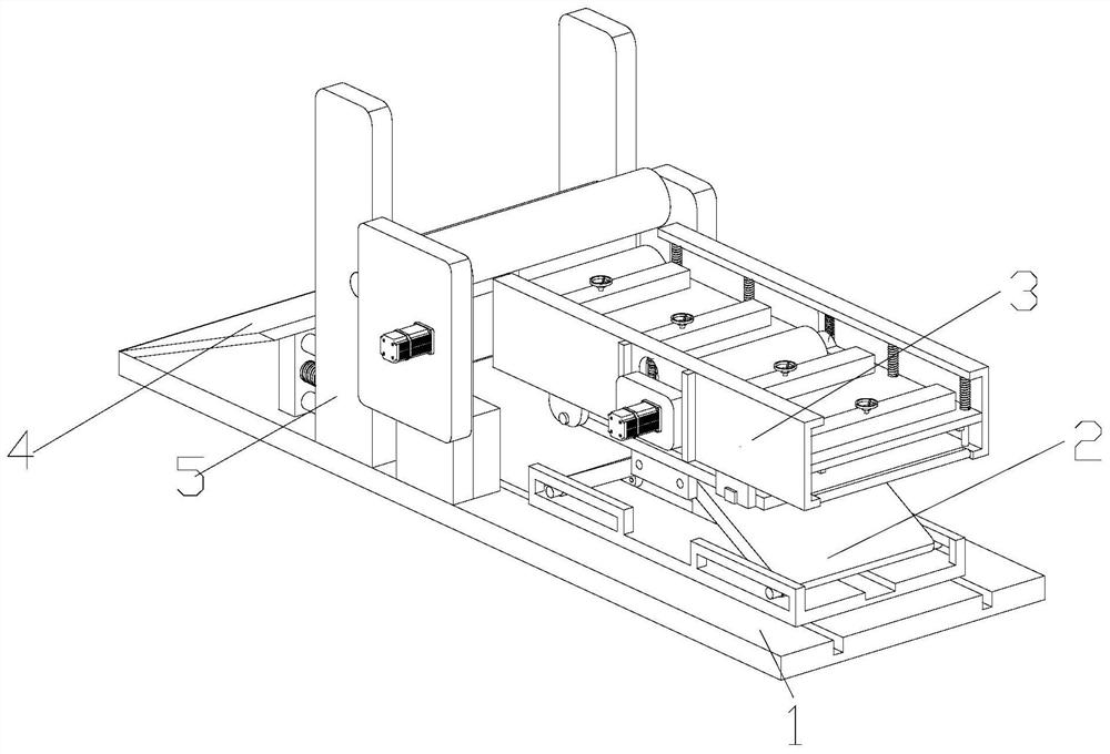
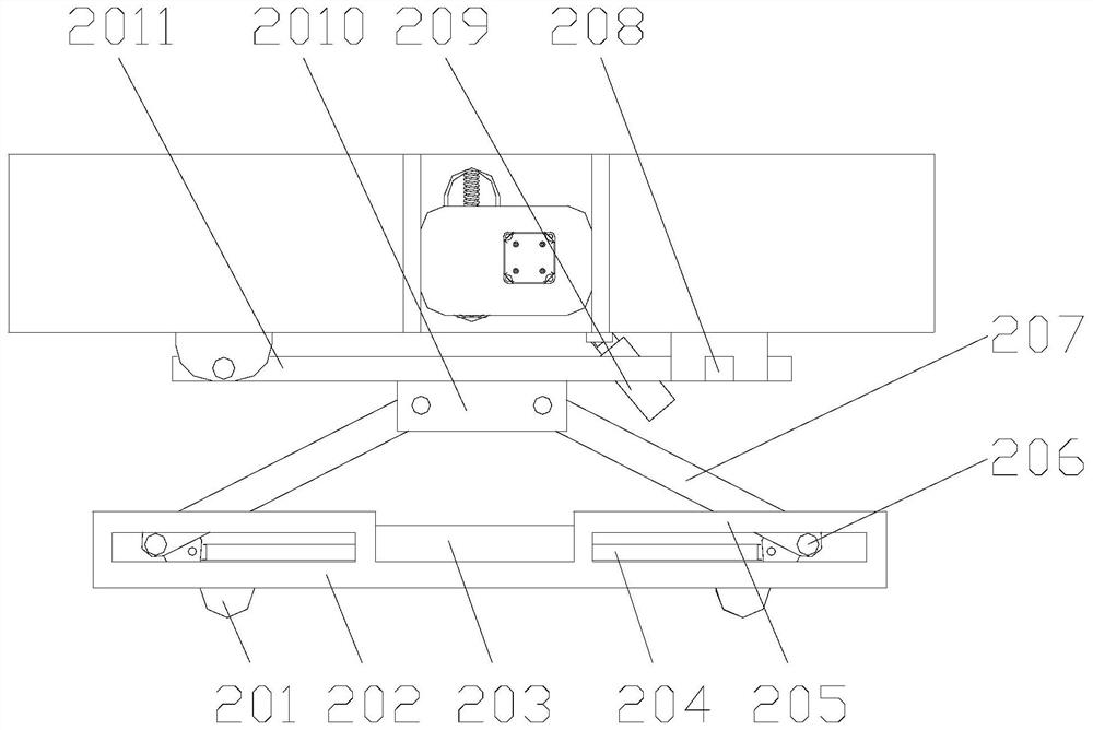
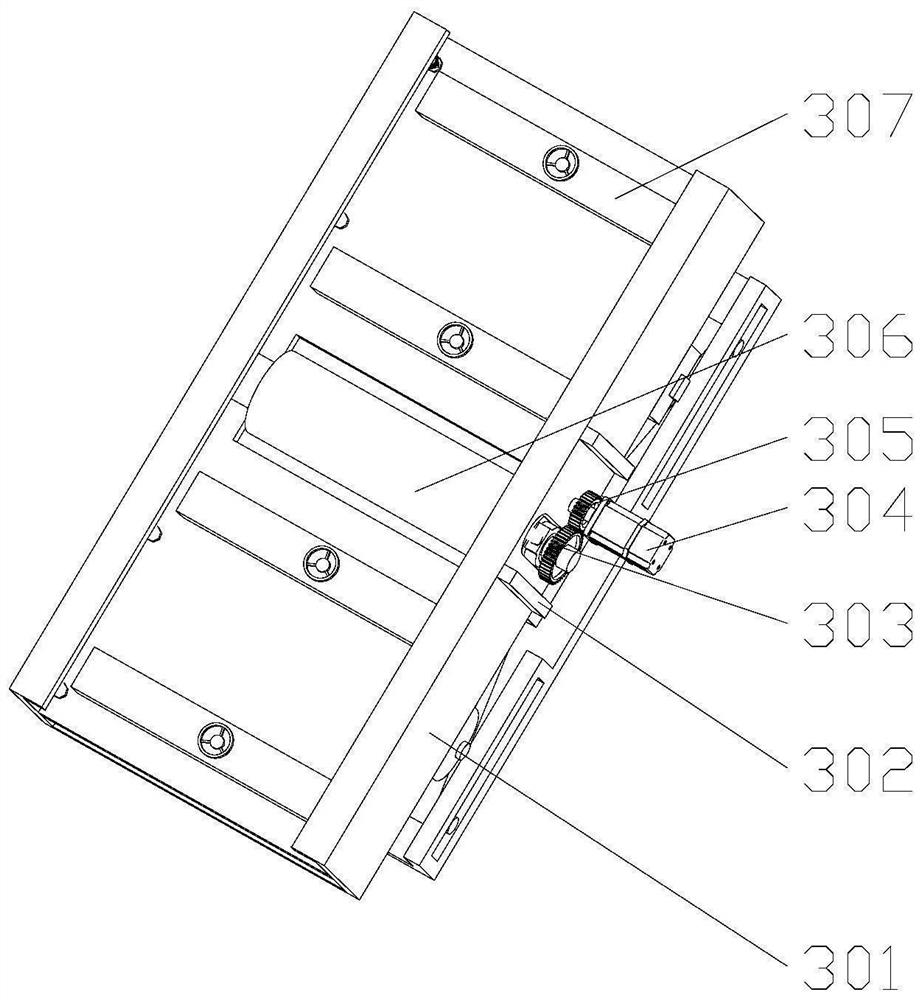
[0035] Attached below Figure 1-11 , clearly and completely describe the technical solutions in the embodiments of the present invention, obviously, the described embodiments are only some of the embodiments of the present invention, not all of them. Based on the embodiments of the present invention, all other embodiments obtained by persons of ordinary skill in the art without making creative efforts belong to the protection scope of the present invention.

[0036] In describing the present invention, it should be understood that the terms "longitudinal", "transverse", "upper", "lower", "front", "rear", "left", "right", "vertical", The orientations or positional relationships indicated by "horizontal", "top", "bottom", "inner", "outer", etc. are based on the orientations or positional relationships shown in the drawings, and are only for the convenience of describing the present invention, rather than indicating or It should not be construed as limiting the invention by impl...


PUM


Abstract

The invention discloses a plate rolling machine for steel structure production, which comprises a bottom plate, a plate rolling mechanism is installed on the bottom plate, the plate rolling mechanism is installed in the middle of the bottom plate, and one side of the plate rolling mechanism is arranged on the bottom plate There is a lifting mechanism, and a feeding device is installed on the top of the lifting mechanism, and the feeding device is matched with the plate rolling mechanism, and a blanking plate is installed on the other side of the plate rolling mechanism on the bottom plate. The lifting device of the present invention is convenient for the staff to lift the board, reduces labor intensity, and improves work efficiency. It works normally, and it is convenient to transport the plate to the plate rolling mechanism, which improves the work efficiency. The plate rolling mechanism can adjust the distance between the rotating rollers to ensure that the device can adapt to plates of different thicknesses, which greatly improves the practicability of the device.

Description

technical field [0001] The invention belongs to the technical field of steel structure production, in particular to a plate rolling machine for steel structure production. Background technique [0002] In the field of steel structure processing and manufacturing, the plate rolling machine is a commonly used plate rolling equipment. The plate rolling machine can be used to roll the plate into circular, arc and conical workpieces within a certain range. The plate rolling machine is used During the process, it is necessary to place the required curled plate between the upper roller and the lower roller, and generate torque through the transmission of the upper roller and the lower roller, so that the plate is deformed. In some large plate rolling machine equipment, it is used for the processed The boards are large in size and heavy in weight, so additional lifting equipment and excessive human resources are required to lift the boards for loading. The entire loading process is ...

Claims


Application Information

Patent Timeline
Patent Type & Authority Patents(China)
IPC IPC(8): B21D5/14B21D43/08B21D1/02B21D21/00
CPCB21D5/14B21D43/08B21D1/02B21D21/00
Inventor 叶建学徐群杰孙建俊李娜娜梁云霞
Owner SHANDONG LABOR VOCATIONAL & TECHN COLLEGE
Why Eureka
Try Eureka