Large laser selection melting forming dust removal scanning device and method

A technology of laser selective melting and scanning equipment, applied in the direction of additive processing, etc., can solve the problems of reducing equipment stability, large loss of inert airflow, easy airflow diffusion, etc., to improve equipment stability, improve forming efficiency, and reduce complexity. degree of effect

Active Publication Date: 2020-10-30
AVIC BEIJING AERONAUTICAL MFG TECH RES INST
View PDF4 Cites 8 Cited by
  • Summary
  • Abstract
  • Description
  • Claims
  • Application Information

AI Technical Summary

Problems solved by technology

[0003] At present, the structural layout of blowing and suction ports used in laser selective melting equipment is generally only suitable for equipment with a forming width below 500mm. When the forming width is expanded to a certain extent (such as 500mm), many unavoidable problems will occur, resulting in dust removal. rapidly diminishing effect
For example, in the multi-laser beam array scanning, the dust brought by the upstream forming area of ​​the airflow will weaken the laser power in the downstream form

Method used


Image

  • Large laser selection melting forming dust removal scanning device and method
  • Large laser selection melting forming dust removal scanning device and method
  • Large laser selection melting forming dust removal scanning device and method

Examples


Embodiment Construction

[0032] Embodiments of the present invention will be further described in detail below in conjunction with the accompanying drawings and examples. The detailed description and accompanying drawings of the following embodiments are used to illustrate the principles of the present invention, but cannot be used to limit the scope of the present invention, that is, the present invention is not limited to the described embodiments, without departing from the spirit of the present invention Any modification, substitution and improvement of parts, components and connection methods are covered under.

[0033] It should be noted that, in the case of no conflict, the embodiments in the present application and the features in the embodiments can be combined with each other. The present application will be described in detail below with reference to the accompanying drawings and embodiments.

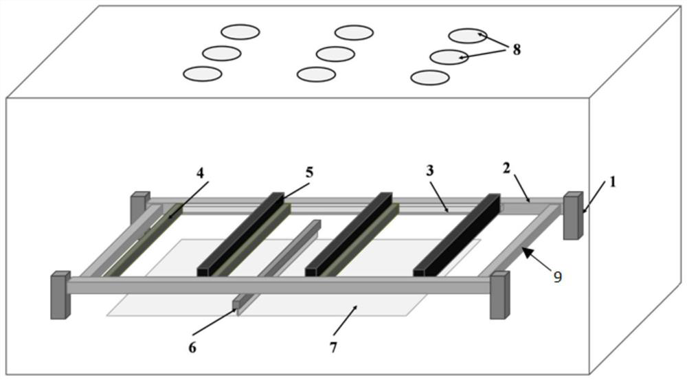
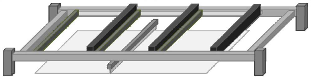
[0034] Figure 1 to Figure 3Shown is the first aspect of the embodiment of the present inventio...


PUM

PropertyMeasurementUnit
Widthaaaaaaaaaa

Abstract

The invention relates to a large laser selection melting forming dust removal scanning device and method. The device includes a plurality of blowing and suction air port units with the same structure,a scraper, a powder bed surface and dynamic focusing vibration mirror groups for the division and scanning of forming areas. The dynamic focusing vibration mirror groups are evenly distributed in multiple columns in the direction of the scraper movement, and the blowing and suction air port units are arranged under each column of the dynamic focusing vibration mirror groups. The blowing and suction air port units include air blowing ports and air suction ports, and the air blowing ports and the air suction ports are connected with an external dust removal filtration system; and air port movement brackets for the support of the blowing and suction air port units, vertical movement guide rails for the vertical movement of the air port movement brackets and horizontal movement guide rails for the horizontal movement of the air port movement brackets are further included, and the blowing and suction air port units are evenly distributed on the air port movement brackets in the direction of the scraper movement. The large laser selection melting forming dust removal scanning device and method can guarantee the forming quality and process consistency of parts, the equipment can run steadily for a long time, and at the same time, the forming efficiency of the equipment is improved.

Description

technical field [0001] The invention relates to the technical field of laser selective melting, in particular to a large-scale laser selective melting forming dust removal scanning device and a scanning method. Background technique [0002] In the existing laser selective melting equipment, the dust generated during the forming process is mainly removed by a set of dust removal and purification system. The dust filtration system including the filter box and the fan outside the warehouse are connected to each other through pipelines to form a closed circulation loop. During the working process, the explosion-proof fan drives the flow of air, and then forms a stable laminar flow above the powder layer between the blowing and suction ports in the forming chamber, and the smoke generated during the forming process is taken away through the suction port and sent to the filter. The air box is filtered, and the obtained pure atmosphere is transported to the forming chamber through...

Claims


Application Information

Patent Timeline
IPC IPC(8): B22F3/105B33Y30/00
CPCB33Y40/00Y02P10/25
Inventor 谢印开李怀学胡全栋张雪峰杨圣昆
Owner AVIC BEIJING AERONAUTICAL MFG TECH RES INST
Why Eureka
Try Eureka