Movable flange end face turning device

A face turning, mobile technology, applied in turning equipment, auxiliary devices, turning equipment, etc., can solve the problems of high cost, reduced work efficiency, waste of time, etc.

Inactive Publication Date: 2020-10-30
南京江宁区上峰国银标准件厂
View PDF0 Cites 0 Cited by
  • Summary
  • Abstract
  • Description
  • Claims
  • Application Information

AI Technical Summary

Problems solved by technology

[0002] The existing processing of the end face of the flange is generally realized by a lathe. When the operator docks the pipe outside, but the flange is too thick and needs to be processed, he needs to go to the facto

Method used


Image

  • Movable flange end face turning device
  • Movable flange end face turning device
  • Movable flange end face turning device

Examples


Embodiment Construction

[0026] The present invention is described in further detail now in conjunction with accompanying drawing. These drawings are all simplified schematic diagrams, which only illustrate the basic structure of the present invention in a schematic manner, so they only show the configurations related to the present invention.

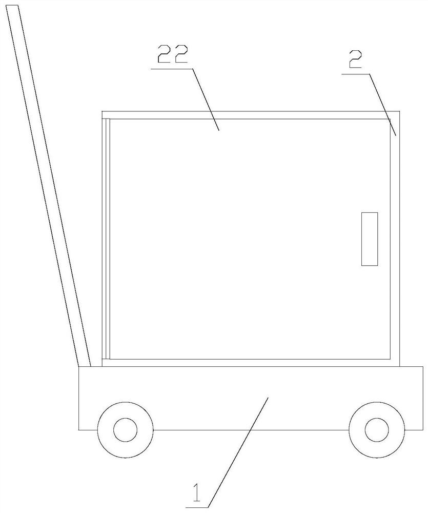
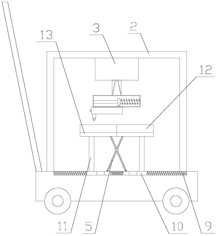
[0027] Such as Figure 1-5 As shown, a mobile flange end face turning device includes a base 1, a fixed box 2, a drive box 3, a drive shaft 4, a turning mechanism and a clamping mechanism, the base 1 is arranged horizontally, and the fixed box 2 is arranged on On the base 1, the drive box 3 is arranged on the top of the fixed box 2 inside, the drive shaft 4 is arranged under the drive box 3, and the drive box 3 is provided with a driving device, and the drive shaft 4 and the drive device connected, the clamping mechanism is arranged on the base 1, the turning mechanism is arranged between the driving box 3 and the clamping mechanism, and both the clamping mec...


PUM


Abstract

The invention relates to a movable flange end face turning device. The movable flange end face turning device comprises a base, a fixing box, a driving box, a driving shaft, a turning mechanism and aclamping mechanism, the clamping mechanism comprises a clamping assembly and a fixing assembly, and the turning mechanism comprises a Morse taper shank, a fixing block, a limiting rod, a lantern ring,a third spring, a connecting rod, a turning tool and a tool rest. According to the movable flange end face turning device, movement of the tool rest is achieved through rotation of the driving deviceand the action of centrifugal force, so that turning of the flange end face is achieved; resetting of the tool rest is achieved through restoring force of the third spring, meanwhile, secondary turning of the flange end face is achieved in the resetting process, at the moment, due to the fact that the rotating speed of turning is suddenly reduced, and the flange end face is turned into spiral shape through inertia rotation, so that the effect of a flange line on the flange end face is achieved; and first-stage clamping of a flange is achieved through the clamping assembly, second-stage clamping of the flange is achieved through the fixing assembly, and the use practicability is improved.

Description

technical field [0001] In particular, the invention relates to a mobile flange face turning device. Background technique [0002] The existing processing of the end face of the flange is generally realized by a lathe. When the operator docks the pipe outside, but the flange is too thick and needs to be processed, he needs to go to the factory, and then the lathe is used to complete the processing. The processing of the flange requires a large cost, not only the processing fee, but also the transportation fee, which wastes time and reduces work efficiency. Contents of the invention [0003] The technical problem to be solved by the present invention is to provide a mobile flange end face turning device in order to overcome the deficiencies of the prior art. [0004] The technical solution adopted by the present invention to solve the technical problem is: a mobile flange end face turning device, including a base, a fixed box, a drive box, a drive shaft, a turning mechanism...

Claims


Application Information

Patent Timeline
IPC IPC(8): B23B5/00B23B3/26B23B25/06B23B27/00
CPCB23B3/26B23B5/00B23B25/06B23B27/00
Inventor 韩平
Owner 南京江宁区上峰国银标准件厂
Why Eureka
Try Eureka