Column welding system

A welding system and column technology, applied in welding equipment, welding equipment, auxiliary welding equipment, etc., can solve the problems of low welding efficiency of column and unsmooth welding operation.

Pending Publication Date: 2020-10-30
华元模块化建筑科技上海有限公司
View PDF12 Cites 4 Cited by
  • Summary
  • Abstract
  • Description
  • Claims
  • Application Information

AI Technical Summary

Problems solved by technology

[0005] The purpose of the present invention is to provide a column welding system to solve

Method used


Image

  • Column welding system
  • Column welding system
  • Column welding system

Examples


Embodiment Construction

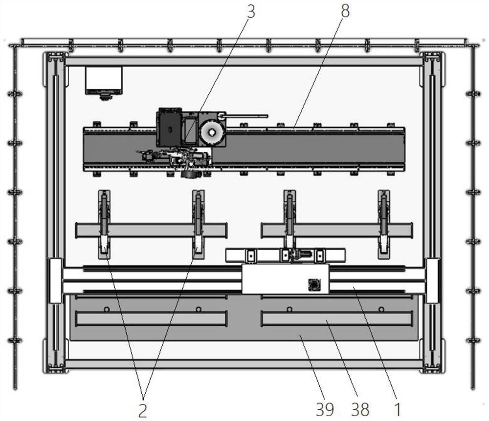
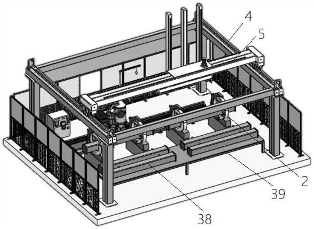
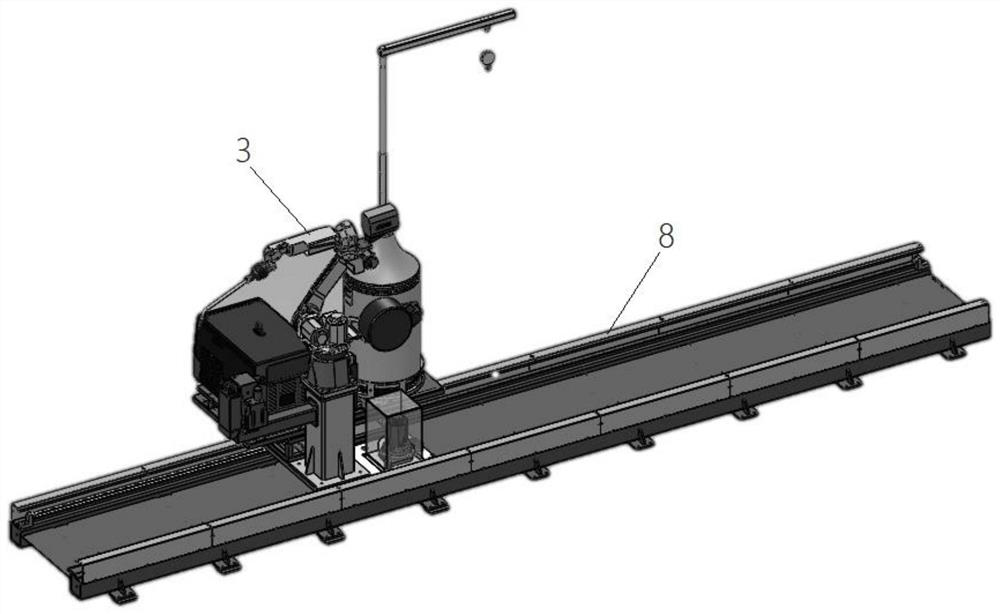
[0030] Such as Figure 1 to Figure 6 As shown, a column welding system includes a truss mechanism 1 , a positioner 2 and a welding robot 3 . Such as Figure 6 As shown, the truss mechanism 1 includes a three-axis slide table and a fixture installed on the Z-axis slide table 5 of the three-axis slide table. The three-axis slide table and the fixture can cooperate to move the workpiece to the positioner; specifically, the present The fixture of the system includes a fixed frame 36 installed on the Z-axis slide table 5, and at least two electromagnets 37 installed on the fixed frame 36. The workpieces involved in this system are also made of magnetically absorbable materials, and the electromagnets 37 are energized Finally, the workpiece can be absorbed, and the structure of the fixture is simple and practical.

[0031] Such as figure 1 and figure 2 As shown, the welding system also includes a buffer station 39, on which a plurality of workpieces 38 can be placed, the buffer...


PUM


Abstract

The invention provides a column welding system which comprises a truss mechanism, a positioner and a welding robot. The truss mechanism comprises a three-axis sliding table and a clamp mounted on thethree-axis sliding table, wherein the three-axis sliding table and the clamp can act in a fit manner to transfer a workpiece to the positioner; the positioner comprises two positioning assemblies which are distributed in a spaced manner to clamp the left and right sides of the workpiece. Each positioning assembly comprises a base, a first clamping part, a second clamping part, a connector and a compacting driving device. The first clamping part is mounted on the top of the base, the second clamping part and the first clamping part are closed to form a clamping part with clamping holes, the clamp can place the workpiece in the two clamping holes flatly, the connector is connected to the second clamping part, the compressing driving device is hinged to the base, an output rod of the compressing driving device is hinged to the connector, and the compressing driving device can overturn upward or can push the second clamping part. The welding system can operate continuously and is high in welding efficiency.

Description

technical field [0001] The invention belongs to the technical field of welding equipment, and in particular relates to a column welding system. Background technique [0002] During the processing of the column, the end panels need to be welded to both ends of the column. In addition, each corner of the column needs to be welded. Therefore, the workpiece needs to be welded at multiple angles. The existing welding system can use a positioner to cooperate with a welding robot. To complete, the processing efficiency is higher. [0003] However, the existing column welding system is usually intermittent processing, which cannot realize continuous production from workpiece loading to unloading, and there is a long waiting time in the middle, so the processing efficiency needs to be improved. [0004] In addition, the clamping of the workpiece by the existing column welding system is an enveloping clamping. If the top corner of the workpiece needs to be welded, it will be blocked ...

Claims


Application Information

Patent Timeline
IPC IPC(8): B23K31/02B23K37/04B23K37/047B23K37/02B23K37/00B25J9/02
CPCB23K31/02B23K37/0435B23K37/047B23K37/0211B23K37/00B25J9/023
Inventor 张文元王鲜团
Owner 华元模块化建筑科技上海有限公司
Why Eureka
Try Eureka