Ear wire automatic thread cutting machine and thread cutting method
A wire cutting machine and ear wire technology, which is applied in metal processing and other directions, can solve the problems of difficulty in grasping precision and low efficiency of manual cutting, and achieve the effects of improving equipment precision, saving electricity and improving cutting precision.
- Summary
- Abstract
- Description
- Claims
- Application Information
AI Technical Summary
Problems solved by technology
Method used
Image
Examples
Embodiment 1
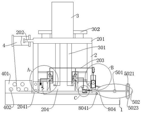
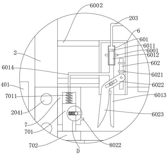
[0038] refer to Figure 1-6 , an automatic ear wire cutting machine, including a base 1 and a motor 5 fixedly connected to the base 1, a support 2 is fixedly connected to the base 1, a pair of cutting boxes 6 are fixedly connected to the support 2, and a passive cylinder is fixedly connected to the cutting box 6 601, the passive piston plate 6011 is slidingly connected to the passive cylinder 601, the passive piston rod 6012 is fixedly connected to the bottom of the passive piston plate 6011, the right tangent cutter 6013 is fixedly connected to the bottom of the passive piston rod 6012, and the fixed rod 602 is fixedly connected to the tangent box 6 , the fixed rod 602 is rotatably connected with a left tangent cutter 6023, the left tangent cutter 6023 is connected with the right tangent cutter 6013, the output end of the motor 5 is fixedly connected with a rotating shaft 501, and the rotating shaft 501 is fixedly connected with an elliptical wheel 502. A cylindrical shifting...
Embodiment 2
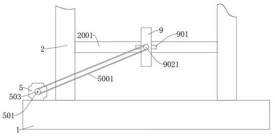
[0043] refer to figure 1 and figure 2 , is basically the same as that of Embodiment 1, and furthermore, the drive unit includes an active cylinder 904, the active cylinder 904 is fixedly connected to the passive cylinder 601 through the air pipe 203, the active cylinder 904 is fixedly connected to the bracket 2, and the bracket 2 is fixedly connected to Drive cylinder 9, hollow rack 903 is slidingly connected in driving cylinder 9, active piston plate 9032 is slidingly connected in active cylinder 904, active piston plate 9032 is fixedly connected on hollow rack 903 through active piston rod 9031, hollow rack 903 A half gear 902 is connected to the internal meshing, a driven wheel 9021 is fixedly connected to the half gear 902, a driving wheel 503 is fixedly connected to the rotating shaft 501, and the driving wheel 503 is rotationally connected with the driven wheel 9021 through a belt 5001, and the half gear 902 is connected to the hollow rack 903 When rotating internally,...
Embodiment 3
[0046] refer to figure 1 , is basically the same as Embodiment 1, furthermore, the clamp bar 804 is rotatably connected with a roller 8041, and the base 1 is provided with a rolling groove cooperating with the roller 8041, and the roller 8041 can reduce the friction force when the clamp bar 804 slides, saving Electricity improves device accuracy.
PUM
 Abstract
Description
Claims
Application Information
 - R&D
- Intellectual Property
- Life Sciences
- Materials
- Tech Scout
- Unparalleled Data Quality
- Higher Quality Content
- 60% Fewer Hallucinations
Browse by: Latest US Patents, China's latest patents, Technical Efficacy Thesaurus, Application Domain, Technology Topic, Popular Technical Reports.
© 2025 PatSnap. All rights reserved.Legal|Privacy policy|Modern Slavery Act Transparency Statement|Sitemap|About US| Contact US: help@patsnap.com


