
Efficient architectural furniture timber cutting device

A cutting device and wood technology, applied in the direction of wood processing equipment, manufacturing tools, multi-purpose machinery, etc., can solve the problems of poor wood flatness, wood bending deformation, wood cutting deformation, etc., to ensure accuracy, avoid deformation, Smooth wood cut surface effect

Active Publication Date: 2020-10-30
ZHONGYUAN ENGINEERING COLLEGE
View PDF8 Cites 2 Cited by
  • Summary
  • Abstract
  • Description
  • Claims
  • Application Information

AI Technical Summary

Problems solved by technology

[0002] The use of wooden furniture in daily life is becoming more and more common. When making wooden furniture, the wood must be cut, and the furniture can only be made after the cutting is completed. Most of the existing wood cutting devices use the push method to cut. When the size of the wood is large, the wood will be bent and deformed, resulting in poor flatness of the cut wood, and there is no corresponding pressing device at the cutting place, resulting in deformation of the wood cutting place during cutting, which affects the quality of the wood. quality, and need to be polished and trimmed after the cutting is completed, which affects the work efficiency. In view of the above problems, the present invention proposes a high-efficiency building furniture wood cutting device

Method used


Image

  • Efficient architectural furniture timber cutting device
  • Efficient architectural furniture timber cutting device
  • Efficient architectural furniture timber cutting device

Examples


Embodiment Construction

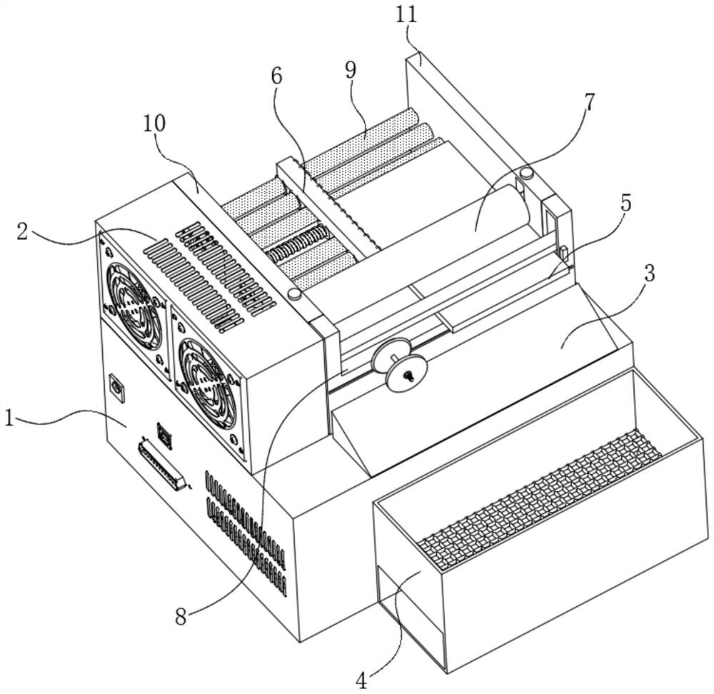
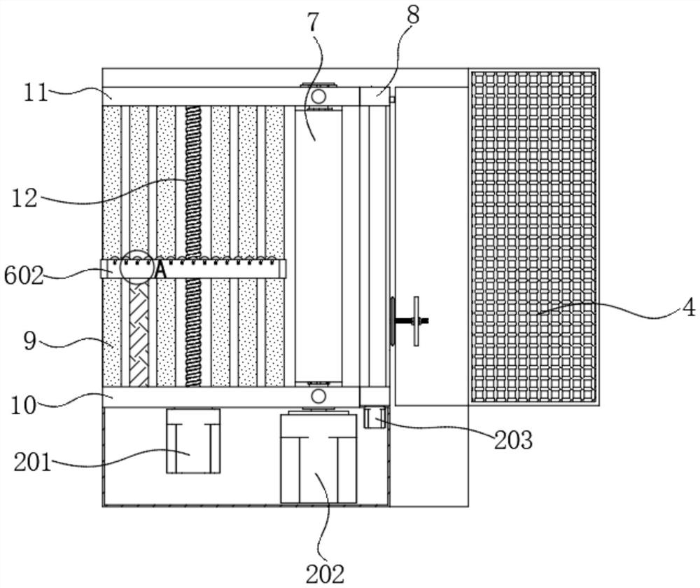
[0030] see Figure 1-7 , in an embodiment of the present invention, a high-efficiency building furniture wood cutting device includes a base 1, a straightening assembly 6, a conveying assembly 7, a cutting assembly 8 and a receiving assembly, wherein a power box 2 is fixed on the top side of the base 1 , used to provide power for the centralizing assembly 6, the conveying assembly 7 and the cutting assembly 8;

[0031] One side of the power box 2 is fixed with a side plate 10, and the opposite side of the side plate 10 is equipped with a side plate 11 fixed on the top of the base 1, and a screw is arranged between the side plate 10 and the side plate 11. One 12. The straightening assembly 6 and the conveying assembly 7, two sets of rollers 9 are symmetrically arranged on both sides of the screw 12, and each set of rollers 9 includes three rollers 9, and the side plate 10 The cutting assembly 8 is arranged on the right side of the second side plate 11, and the receiving assemb...


PUM


Abstract

The invention discloses an efficient architectural furniture timber cutting device which comprises a base, a straightening assembly, a conveying assembly, a cutting assembly and a receiving assembly,wherein a power box is fixed to the top end of the base for providing power to the device, a side plate I is fixed to one side of the power box, a side plate II is fixed to the side, far away from thepower box, of the top end of the base, a plurality of rollers I are rotatably arranged between the side plate I and the side plate II, and the straightening assembly is slidably arranged on the rollers I, so that a condition that the cutting surface is not smooth enough as a timber which is cut is deflected. The conveying assembly is arranged between the discharge ends of the side plate I and theside plate II. The cutting assembly is fixed at the end close to the conveying assembly. The receiving assembly is fixed on one side of the base and can collect the cut timber, and saw dust can fallat the bottom end of the collecting assembly.

Description

technical field [0001] The invention relates to the field of furniture wood cutting, in particular to a high-efficiency building furniture wood cutting device. Background technique [0002] The use of wooden furniture in daily life is becoming more and more common. When making wooden furniture, the wood must be cut, and the furniture can only be made after the cutting is completed. Most of the existing wood cutting devices use the push method to cut. When the size of the wood is large, the wood will be bent and deformed, resulting in poor flatness of the cut wood, and there is no corresponding pressing device at the cutting place, resulting in deformation of the cutting part of the wood during cutting, which affects the quality of the wood. quality, and need to be polished and trimmed after the cutting is completed, which affects the work efficiency. Aiming at the above problems, the present invention proposes a high-efficiency building furniture wood cutting device. Conte...

Claims


Application Information

Patent Timeline
IPC IPC(8): B27C9/02B27G3/00
CPCB27C9/02B27G3/00
Inventor 宋晓庆李琼马骁
Owner ZHONGYUAN ENGINEERING COLLEGE
Learn More