Washing machine with drying function
A washing machine and function technology, applied in the field of washing machines with drying function, can solve the problems of increasing power consumption cost, reducing drying efficiency, wasting resources and the like
Pending Publication Date: 2020-10-30
QINGDAO HAIER DRUM WASHING MACHINE +1
6 Cites 0 Cited by
AI-Extracted Technical Summary
Problems solved by technology
Hot air passing between the inner and outer cylinders will cause a waste of resources, which not ...
Method used
Annular support rib 6 is provided with a circle along the inner side of urceolus bottom 4, and air outlet 5 circles are in the inside of annular support rib 6, like this, when annular support rib 6 cooperates with the seal at inner tube bottom 3 When in sealed contact, after the drying air is discharged, a circle of sealed barriers can be formed on the outer periphery. In this way, the hot air can only pass through the inner tube 1 and exchange heat with the clothes in the inner tube 1 before it can be discharged from the air outlet 5, and cannot Through the gap channel between the inner cylinder 1 and the outer cylinder 2, the air is directly discharged to the air outlet 5, so that the hot air can be applied to the washed clothes to the maximum extent, saving drying air and reducing energy loss.
In this scheme, one side of the annular sealing ring 7 can form a bifurcated structure, and its end towards the bottom of the tub includes a plurality of free ends, that is, a plurality of contact portions 72 are formed, and the plurality of contact portions 72 can It contacts and seals with the annular support rib 6 at different positions to achieve the effect of multi-stage sealing, further blocks the flow of hot air between the inner cylinder 1 and the outer cylinder 2, and improves the drying efficiency.
The sealing structure that this program is set between the inner tube 1 and the outer tube 2 of the washing machine can stop the drying wind from flowing in the gap between the inner tube 1 and the outer tube 2, and avoid hot blast from between the inner tube and the outer tube. The gap between them is directly discharged from the air outlet, which can maximize the application of hot air on the washed clothes, save drying air, reduce energy loss, improve the drying efficiency of the washing machine, reduce energy consumption, and save resources.
[0044] By cooperating with the seal fixed at the bottom 3 of the inner tube and the support fixed at the bottom 4 of the outer tube, when the washing machine dehydrates, the seal is connected to the outer tub...
Abstract
The invention discloses a washing machine with a drying function. The washing machine with the drying function includes an inner drum and an outer drum, and the inner drum is coaxially arranged insidethe outer drum; the rear part of the outer drum is provided with an air outlet; and a sealing structure that can achieve communicating or blocking between a gap between the inner drum and the outer drum and the air outlet is arranged between the inner drum and the outer drum. According to the invention, the sealing structure arranged between the inner drum and the outer drum of the washing machine can block drying air in the gap from being directly discharged from the air outlet, and can ensure normal drainage, thus the sealing structure can not only maximize the application of hot air to clothes after washing, save drying air, reduce energy loss, but also improve the drying efficiency of the washing machine, reduce energy consumption, and save resources.
Application Domain
Other washing machinesWashing machine with receptacles +2
Technology Topic
Process engineeringMechanical engineering +2
Image
Examples
- Experimental program(1)
Example Embodiment
[0040] Example one
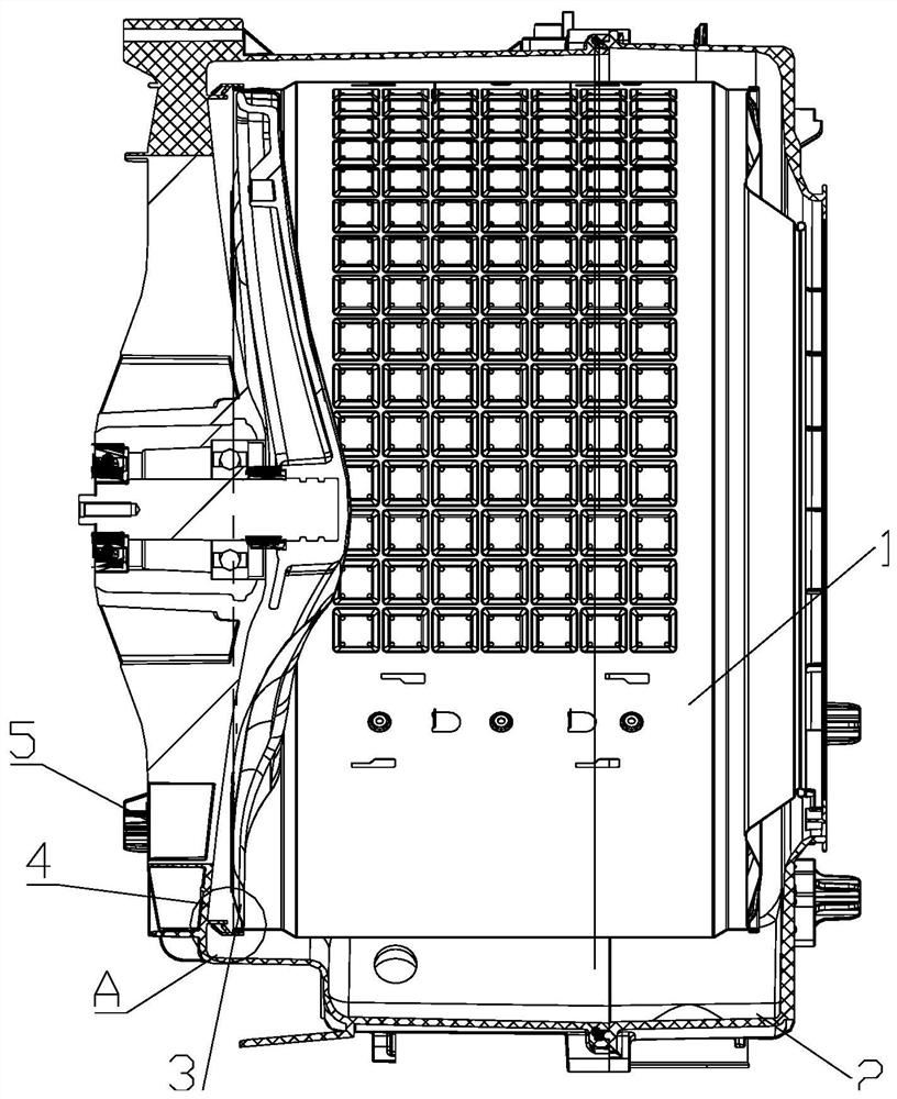
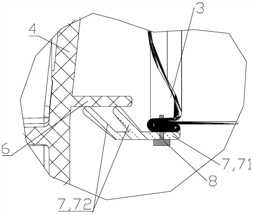
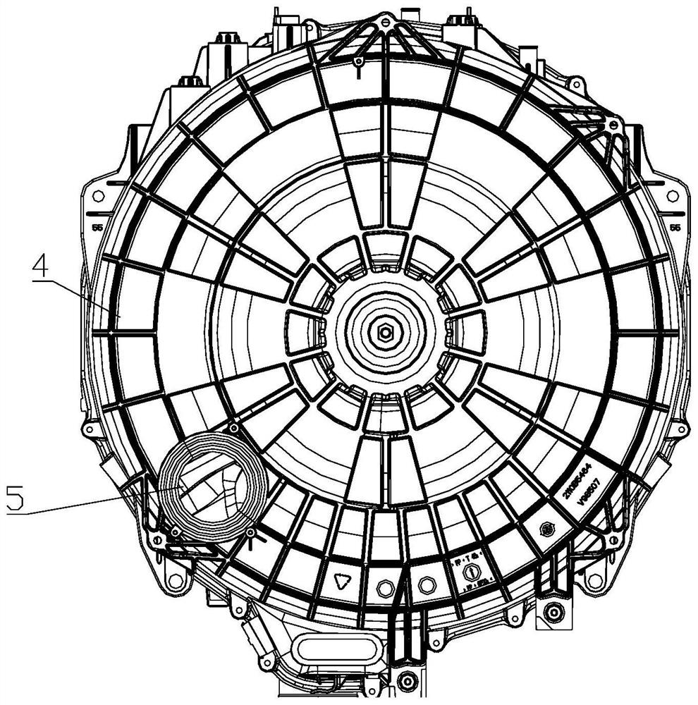
[0041] Such as Figure 1 to Figure 3 As shown, the sealing structure of this embodiment includes a supporting member and a sealing member that can be contacted or separated in a sealed manner. The supporting member is fixed at the rear of the outer cylinder 2/the rear of the inner cylinder 1, and the sealing member is fixed at the rear of the inner cylinder 1. / Corresponding position at the rear of the outer cylinder 2.
[0042] In this embodiment, the sealing structure includes two parts arranged in cooperation with each other, that is, a support member and a sealing member. The setting positions of the supporting member and the sealing member are matched and corresponding to each other. When the support is fixed at the rear of the outer cylinder 2, the seal is fixed at the corresponding position at the rear of the inner cylinder 1; when the support is fixed at the rear of the inner cylinder 1, the seal is fixed at the corresponding position at the rear of the outer cylinder 2. In this way, under different circumstances, the supporting member and the sealing member can be in contact with or separated from each other to achieve the purpose of blocking or opening the channel formed by the gap between the inner cylinder 1 and the outer cylinder 2.
[0043] As a specific embodiment, in order to control the opening/closing state of the sealing structure through the change of the rotation state of the inner cylinder 1, the support is provided on the side of the outer cylinder bottom 4 facing the inner cylinder 1, and the seal is provided The bottom 3 of the inner cylinder faces the side of the outer cylinder 2. During drying, the sealing member is in sealing contact with the supporting member to block the drying wind, and during dehydration, the sealing member is separated from the supporting member to allow water flow to pass.
[0044] Through the matching arrangement of the sealing member fixed to the bottom 3 of the inner tub and the support member fixed to the bottom 4 of the outer tub, when the washing machine is dehydrated, the sealing member is separated from the support member of the outer tub 2 due to the rotation of the motor and the centrifugal force. , The two are no longer in contact, and the water discharged from the inner cylinder 1 can pass through the gap between the support and the seal, so it does not affect the water flow to the outlet of the outer cylinder 2 below; and when the drying speed is low, the seal In contact with the supporting ribs of the bottom 4 of the outer cylinder, the channel formed by the gap between the inner cylinder 1 and the outer cylinder 2 is blocked, thereby preventing hot air from flowing through the gap between the inner and outer cylinders 2. In this way, the efficiency of the dryer can be improved, the loss of hot air can be reduced, resources can be saved, and costs can be reduced.
[0045] The seal can be made of deformable material. The seal can be deformed under the action of the centrifugal force generated by the high-speed rotation of the inner cylinder 1 so as to be separated from the support; when the inner cylinder 1 rotates at a low speed, the centrifugal force becomes smaller or even close to no time , The sealing element can return to its original state by itself, sealing contact with the supporting element, achieving the effect of sealing and blocking. For example, the seal may be made of rubber material.
[0046] Further, the bottom of the outer cylinder 2 has an air outlet 5. In order to prevent the hot air entering the gap between the inner cylinder 1 and the outer cylinder 2 from being directly discharged from the air outlet 5, a sealing structure may be provided on the outer periphery of the air outlet 5. Between the inner cylinder 1 and the outer cylinder 2.
[0047] As a specific embodiment, the support member is an annular support rib 6 protruding toward the bottom 3 of the inner cylinder relative to the bottom 4 of the outer cylinder, and the air outlet 5 is located inside the annular support rib 6.
[0048] The annular support rib 6 is arranged in a circle along the inner side of the bottom 4 of the outer cylinder, and the air outlet 5 is circled inside the annular support rib 6. In this way, when the annular support rib 6 and the seal of the inner cylinder bottom 3 cooperate and sealingly contact After the drying air is discharged, a seal can be formed on the outer circumference. In this way, the hot air can only pass through the inner tube 1 and exchange heat with the clothes in the inner tube 1 before it can be discharged from the air outlet 5, but cannot pass through the inner tube The gap channel between 1 and the outer cylinder 2 flows directly to the air outlet 5 to discharge, which can maximize the application of hot air to the clothes after washing, save drying air and reduce energy loss.
[0049] The annular support rib 6 can be a separate component fixed inside the bottom 4 of the outer cylinder, or it can be integrally formed with the bottom 4 of the outer cylinder. The inner side of the bottom 4 of the outer cylinder partially protrudes in a circle toward the inner cylinder bottom 3 side. The annular support ribs 6 can be made of plastic materials or metal materials. As a more preferable solution, the annular support rib 6 may be a plastic part or a metal part, and is fixedly installed inside the bottom 4 of the outer cylinder.
[0050] The annular supporting rib 6 protrudes annularly toward the side of the bottom 3 of the inner cylinder, and therefore, both the outer periphery and the inner periphery thereof have a certain surface. In order to achieve a better sealing effect when in contact with the sealing element, the outer peripheral surface and/or the inner peripheral surface of the annular support rib 6 is a smooth surface, wherein at least the surface in contact with the sealing element is a smooth surface.
[0051] Further, in order to cooperate with the annular support rib 6 as a support, the seal is an annular sealing ring 7. The annular sealing ring 7 includes a fixing portion 71 and a contact portion 72 in the axial direction, and the fixing portion 71 is fixed to the bottom 3 of the inner cylinder. , The contact portion 72 extends toward the bottom 4 of the outer cylinder; the contact portion 72 can be in sealed contact with the annular support rib 6 or separated by a certain distance.
[0052] The annular sealing ring 7 is made of deformable material, for example, a rubber ring. The annular sealing ring 7 is fixedly arranged on the side of the inner cylinder bottom 3 facing the outer cylinder bottom 4. In this solution, the annular sealing ring 7 has a certain length in the axial direction, and the end close to and fixed to the bottom 3 of the inner cylinder is a fixed portion 71, and the end extending toward the bottom 4 of the outer cylinder is a free end, and the free end is connected to an annular support The rib 6 is in sealed contact, that is, the contact portion 72. In this solution, the fixing portion 71 and the contact portion 72 are integrally formed, and the fixing portion 71 ensures the fixing effect of the annular sealing ring 7, and the contact portion 72 achieves the effect of sealing contact or separation with the annular support rib 6 through its deformation effect.
[0053] During drying, the contact portion 72 seals against the side wall of the annular support rib 6. During dehydration, there is a certain gap between the contact portion 72 and the side wall of the annular support rib 6. Thereby saving drying wind, reducing energy loss, and ensuring drainage effect.
[0054] Further, in order to realize the separation state between the annular sealing ring 7 and the annular supporting rib 6 when the inner cylinder 1 rotates at a high speed, and allowing water to pass through, the annular sealing ring 7 is located on the outer periphery of the annular supporting rib 6, and during drying, The contact portion 72 of the annular sealing ring 7 seals against the outer peripheral side wall of the annular support rib 6.
[0055] In this solution, the diameter of the annular sealing ring 7 is greater than the diameter of the annular supporting rib 6 and is installed on the outer periphery of the annular supporting rib 6, so that the contact portion 72 of the annular sealing ring 7 toward the end of the outer cylinder bottom 4 can be removed from the annular supporting rib The outer periphery of 6 touches it. Since the centrifugal force generated when the inner cylinder 1 rotates is directed away from the center of the inner cylinder 1, the contact portion 72 can deform in a direction away from the center of the inner cylinder 1 under the left and right action of the centrifugal force, that is, it will deviate from the outer shape. The contact portion 72 is no longer in contact with the outer peripheral side wall of the annular support rib 6, but generates a certain gap to allow the water discharged from the inner cylinder 1 to pass through, avoid water accumulation and ensure normal drainage effect.
[0056] Further, in order to achieve a better contact and sealing effect and separation effect, the diameter of the end of the contact portion 72 close to the annular support rib 6 is smaller than the diameter of the connection position with the fixing portion 71.
[0057] In this solution, the fixed portion 71 has the same diameter everywhere, while the diameter of each portion in the contact portion 72 is different, so as to achieve the supporting effect. Since the annular sealing ring 7 is located on the outer circumference of the annular support rib 6, the contact portion 72 contacts and seals from the outer circumference of the annular support rib 6, the freely extending end of the contact portion 72 has a smaller diameter, and the diameter of the portion close to the fixed portion 71 is larger In this way, a supporting force can be generated, so that the contact portion 72 can better support on the annular supporting rib 6 during drying.
[0058] As a specific preferred solution, the contact portion 72 gradually extends obliquely toward the center of the inner cylinder 1 along the direction toward the bottom 4 of the outer cylinder, forming a gradually narrowing trumpet shape, which can also generate a supporting force to make the contact portion 72 can be better supported on the annular supporting rib 6 during drying. At the same time, this kind of structure can also easily produce deformation that deviates from the outer periphery under the action of centrifugal force, and the contact portion 72 is separated from the annular support rib 6 and a gap is created, allowing water flow to pass.
[0059] Further, in order to achieve a better sealing effect, the annular sealing ring 7 includes at least two contact portions 72 spaced forward and backward in the axial direction, and each contact portion 72 can seal against the side wall of the annular support rib 6 .
[0060] In this solution, one side of the annular sealing ring 7 may form a bifurcated structure, and its end facing the bottom of the outer barrel includes a plurality of free ends, that is, a plurality of contact portions 72 are formed, and the plurality of contact portions 72 can support the ring The ribs 6 contact and seal at different positions to achieve the effect of multi-stage sealing, further blocking the flow of hot air between the inner cylinder 1 and the outer cylinder 2, and improving the drying efficiency.
[0061] Preferably, each contact portion 72 gradually extends obliquely toward the center of the inner tube 1 along a direction toward the rear of the outer tube 2. In this way, each contact portion 72 is formed into a gradually narrowing trumpet shape, which can also generate multiple supporting forces, so that each contact portion 72 can better support on the annular support rib 6 during drying, which further improves the sealing effect and reduces Heat is lost.
[0062] Further, as a preferred embodiment, the position setting method of the annular support rib 6 and the annular seal ring 7 may include the following methods:
[0063] The annular support ribs 6 are arranged at the position where the bottom 4 of the outer cylinder and the bottom 3 of the inner cylinder are the furthest apart to prevent the inner cylinder 1 and the outer cylinder 2 from colliding. For example, the annular supporting rib 6 can be arranged at the position where the bottom 4 of the outer cylinder is facing the most concave part of the inner cylinder 1, thereby preventing the inner cylinder 1 and the outer cylinder 2 from colliding and ensuring the service life of the annular supporting rib 6 and the annular sealing ring 7. It also avoids cylinder collision and reduces noise.
[0064] The annular support rib 6 may be a separate component, fixed inside the bottom 4 of the outer cylinder, or integrally formed with the bottom 4 of the outer cylinder, formed by a ring protruding partially from the inner side of the bottom 4 of the outer cylinder toward the inner cylinder bottom 3 side.
[0065] The annular sealing ring 7 is sleeved and fixed to the outer peripheral edge of the bottom 3 of the inner cylinder, which is convenient for installation and is also convenient for matching with the annular supporting rib 6.
[0066] Preferably, the fixing portion 71 of the annular sealing ring 7 is fixedly connected to the bottom 3 of the inner cylinder through the connecting member 8. The fixing portion 71 of the annular sealing ring 7 can be fixed to the side of the inner cylinder bottom 3 facing the outer cylinder 2 by screws or bolts.
[0067] In summary, the sealing structure of the present invention can prevent the flow of hot air in the gap between the inner and outer cylinders 2, greatly improving the use efficiency of hot air in the drying device, reducing energy efficiency, accelerating the efficiency of drying clothes, and enabling users to reduce energy efficiency at the same time Dry laundry faster.
[0068] The sealing function is realized by the annular sealing ring 7 fixed at the rear edge of the inner cylinder 1 and the annular supporting rib 6 fixed at the rear of the outer cylinder 2. When the washing machine is dehydrating, the annular sealing ring 7 makes the ring-shaped The sealing ring 7 is separated/opened from the annular support rib 6 of the outer cylinder 2 and does not affect the water flow to the outlet of the outer cylinder 2 below. When the drying speed is low, the annular sealing ring 7 and the annular support rib on the inner side of the outer cylinder 2 6 Sealing contact to prevent hot air from flowing from the gap between the inner and outer cylinders 2, which can improve the efficiency of the dryer, reduce the loss of hot air, save resources, and reduce costs.
PUM


Description & Claims & Application Information
We can also present the details of the Description, Claims and Application information to help users get a comprehensive understanding of the technical details of the patent, such as background art, summary of invention, brief description of drawings, description of embodiments, and other original content. On the other hand, users can also determine the specific scope of protection of the technology through the list of claims; as well as understand the changes in the life cycle of the technology with the presentation of the patent timeline. Login to view more.