Eureka AIR delivers breakthrough ideas for toughest innovation challenges, trusted by R&D personnel around the world.

Reinforced concrete retaining wall mold and mounting method thereof

An installation method and a technology of concrete retaining walls, which are applied to the joints of formwork/formwork/working frames, artificial islands, underwater structures, etc., can solve the cumbersome and complicated construction process of retaining walls, wasteful reinforcement materials, and retaining walls. The complex installation process of the wall and other problems can be achieved to save steel materials, improve convenience, and facilitate recycling.

Inactive Publication Date: 2020-10-30
上海河道建设有限公司
View PDF4 Cites 0 Cited by
  • Summary
  • Abstract
  • Description
  • Claims
  • Application Information

AI Technical Summary

Problems solved by technology

[0003] In the relevant technical group, in the construction of the retaining wall of the reinforced concrete structure, after the pouring of the retaining wall is completed, some steel bars will protrude out of the retaining wall, and the protruding steel bars need to be cut off, which makes the construction process of the retaining wall more cumbersome and complicated, and Waste of rebar material is more
[0004] In view of the related technologies mentioned above, the inventor believes that there is a defect that the installation process of the retaining wall is complicated and wastes materials

Method used


Image

  • Reinforced concrete retaining wall mold and mounting method thereof
  • Reinforced concrete retaining wall mold and mounting method thereof
  • Reinforced concrete retaining wall mold and mounting method thereof

Examples


Embodiment Construction

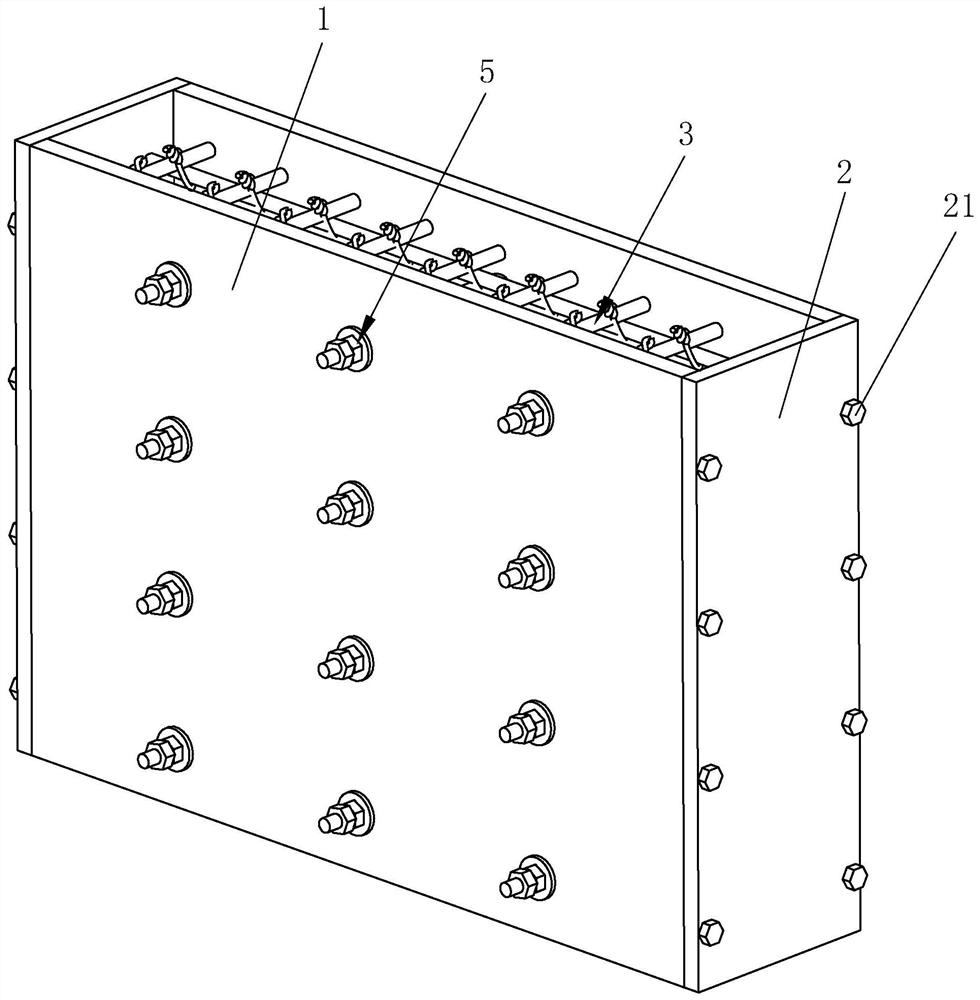
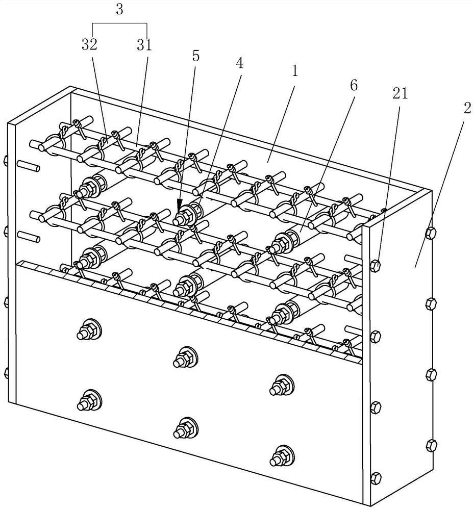
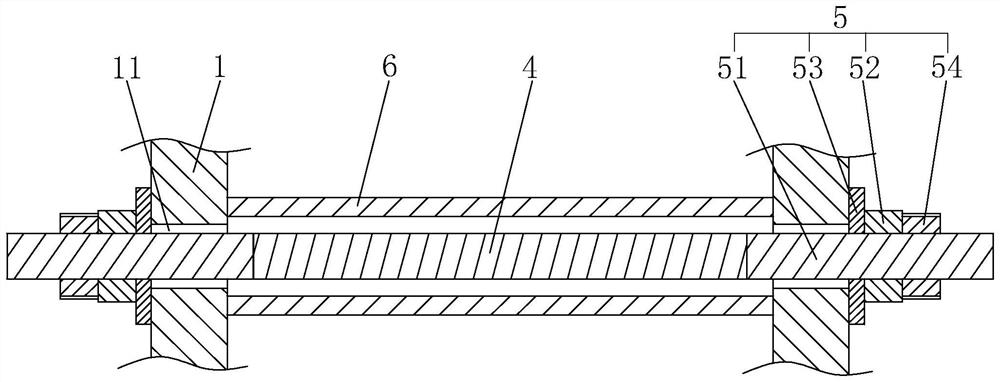
[0053] Attached to the following Figure 1-5 This application will be described in further detail.

[0054] The embodiment of the present application discloses a reinforced concrete retaining wall mold. refer to figure 1, the mold includes two main formwork 1 and two side formwork 2, the main formwork 1 is arranged vertically, the two main formwork 1 are arranged parallel to each other and spaced apart, and the two side formwork 2 are respectively arranged on both sides of the two main formwork 1, And the two ends of the side formwork 2 are detachably connected with the two main formwork 1 respectively, so that the two main formwork 1 and the two side formwork 2 are spliced ​​together to form a pouring space that is compatible with the retaining wall, and a steel skeleton is provided in the pouring space. 3.

[0055] refer to figure 2 and image 3 , a plurality of connecting rods 4 are arranged between the two main formwork 1, the connecting rod 4 is located between the ...


PUM


Abstract

The invention relates to a reinforced concrete retaining wall mold and a mounting method thereof. The reinforced concrete retaining wall mold comprises two main formworks and two side formworks, wherein the two main formworks and the two side formworks are spliced to form a pouring space matched with a retaining wall, a steel reinforcement framework is arranged in the pouring space, a plurality ofconnecting rods are arranged between the two main formworks, and the connecting rods are inserted into the steel reinforcement framework; connecting mechanisms are arranged at the two ends of the connecting rods, the two connecting mechanisms correspond to the two formworks in a one-to-one mode, and the connecting rods are connected to the two main formworks through the two connecting mechanisms;and the connecting rods are further sleeved with protective sleeves, the diameter of the connecting rods is smaller than the inner diameter of the protective sleeves, and the two ends of the protective sleeves abut against the two main formworks. The reinforced concrete retaining wall mold has the effects of improving the convenience of mounting the retaining wall and reducing the waste of reinforcing steel bar materials.

Description

technical field [0001] The present application relates to the field of river channel retaining wall structures, in particular to a reinforced concrete retaining wall mould and an installation method thereof. Background technique [0002] The retaining wall is an important protective structure used in water conservancy projects, which can effectively protect both sides of the river from the scour of the river. At present, most of the retaining walls adopt reinforced concrete structure, and reinforced concrete structure is also called reinforced concrete structure. a composite material. [0003] In the relevant technical group, in the construction of the retaining wall of the reinforced concrete structure, after the retaining wall is poured, some steel bars will protrude out of the retaining wall. There is a lot of wasted steel material. [0004] In view of the above-mentioned related art, the inventor believes that there are defects in that the installation process of the ...

Claims


Application Information

Patent Timeline
IPC IPC(8): E02D29/02E02B3/06E04G17/065
CPCE02B3/066E02D29/0275E04G17/0655
Inventor 钱培庆奕卫江凡宗贵
Owner 上海河道建设有限公司
Why Eureka
Eureka Blog
Learn More