Buildings with Pedestal-Slab Basement Structure
A technology for basement and construction, applied in the direction of construction, building components, building structure, etc., can solve the problem of large amount of reinforcement for foundation beams, and achieve the requirements of reducing the depth of soil and rock excavation, optimizing the construction process, and the effect of reasonable stress.
- Summary
- Abstract
- Description
- Claims
- Application Information
AI Technical Summary
Problems solved by technology
Method used
Image
Examples
Embodiment 1
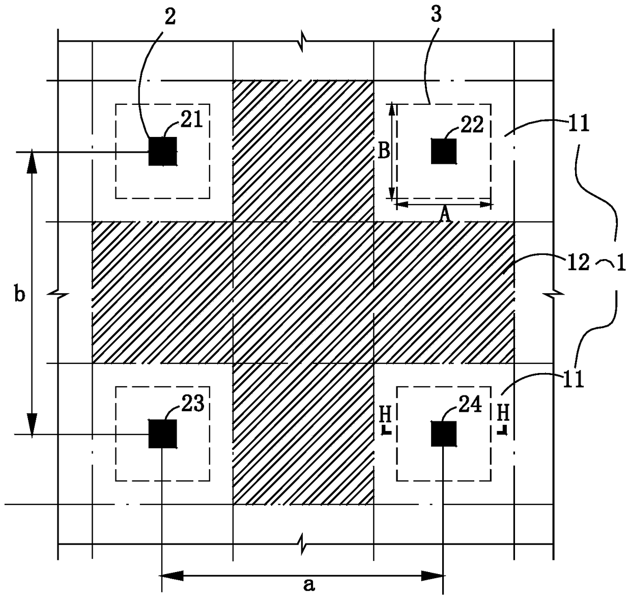
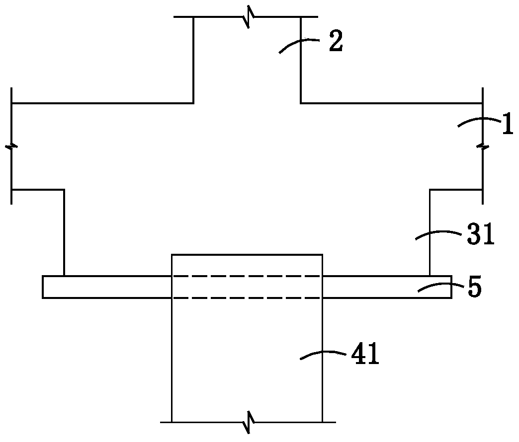
[0045] Present embodiment provides a kind of floor is the building of 10 floors, is provided with basement structure in this building, as figure 1 and figure 2 As shown, the basement part of the basement structure includes a flat plate 1 and a support 3 supported below the flat plate 1, and columns 2 perpendicular to the flat plate 1 are respectively arranged above the flat plate 1 at positions corresponding to each support, and on each support A support pile 41 is provided below the seat. Wherein, the projections of the columns 2 on the plate 1 are distributed in a rectangular array, the horizontal column spacing is a, and the vertical column spacing is b.
[0046] Specifically, the column 2 of this embodiment includes four columns 21, 22, 23, 24, and the projections of the columns 21, 22, 23, 24 on the plate 1 are located at the upper left, upper right, lower left and lower right of the plate 1 respectively. , the four form a rectangular array distribution. Among them, t...
Embodiment 2
[0053] Present embodiment provides a kind of floor is the building of 6 floors, is provided with basement structure in this building, as Figure 5 and Figure 6 As shown, the basement part of the basement structure includes a flat plate 1 and a support 3 supported below the flat plate 1, and columns 2 perpendicular to the flat plate 1 are respectively arranged above the flat plate 1 at positions corresponding to each support, and on each support A support pile 41 is provided below the seat. Wherein, the projections of the columns 2 on the plate 1 are distributed in a rectangular array, the horizontal column spacing is a, and the vertical column spacing is b.
[0054] Specifically, the column 2 of this embodiment includes four columns 21, 22, 23, 24, and the projections of the columns 21, 22, 23, 24 on the plate 1 are located at the upper left, upper right, lower left and lower right of the plate 1 respectively. , the four form a rectangular array distribution. Among them, t...
Embodiment 3
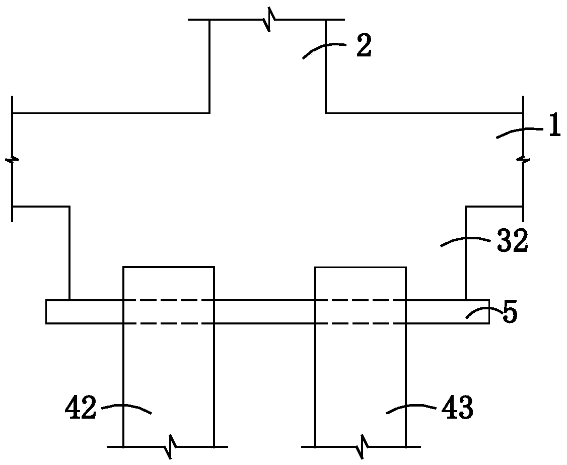
[0060] Present embodiment provides a kind of floor is the building of 5 floors, is provided with basement structure in this building, as Figure 8 and Figure 9As shown, the basement part of the basement structure includes a flat plate 1 and a support 3 supported below the flat plate 1, and columns 2 perpendicular to the flat plate 1 are respectively arranged above the flat plate 1 at positions corresponding to each support, and on each support A support pile 41 is provided inside or below the seat. Wherein, the projections of the columns 2 on the plate 1 are distributed in a rectangular array, the horizontal column spacing is a, and the vertical column spacing is b.
[0061] Specifically, the column 2 of this embodiment includes four columns 21, 22, 23, 24, and the projections of the columns 21, 22, 23, 24 on the plate 1 are located at the upper left, upper right, lower left and lower right of the plate 1 respectively. , the four form a rectangular array distribution. Amon...
PUM
 Abstract
Description
Claims
Application Information
 - R&D
- Intellectual Property
- Life Sciences
- Materials
- Tech Scout
- Unparalleled Data Quality
- Higher Quality Content
- 60% Fewer Hallucinations
Browse by: Latest US Patents, China's latest patents, Technical Efficacy Thesaurus, Application Domain, Technology Topic, Popular Technical Reports.
© 2025 PatSnap. All rights reserved.Legal|Privacy policy|Modern Slavery Act Transparency Statement|Sitemap|About US| Contact US: help@patsnap.com


