Use method of automatic drainage system for water conservancy project construction

An automatic drainage and water conservancy engineering technology, applied in waterway systems, drainage structures, water/sewage treatment, etc., can solve the problems of delayed construction progress, insignificant effects, and low drainage efficiency.

Pending Publication Date: 2020-10-30
山东润康水务有限公司
View PDF0 Cites 3 Cited by
  • Summary
  • Abstract
  • Description
  • Claims
  • Application Information

AI Technical Summary

Problems solved by technology

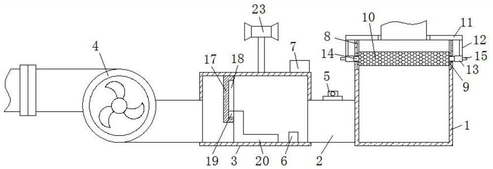
[0003] The purpose of the present invention is to provide a method for using an automatic drainage system for water conservancy construction, which has the advantages of safety and solves the problem that the traditional drainage device has a simple structure, does not constitute a certain drainage system, has a low degree of automation, low drainage efficiency, and has no obvious effect , the traditional drainage devices are basically operated manually, which often leads to untimely drainage and delays in the progress of the construction. It is difficult to meet the needs of construction personnel and the market, and the existing drainage system will be silted up during the drainage process The situation of silting is not easy to be found, and the occurrence of silting will increase the power of the pump and even cause its damage

Method used


Image

  • Use method of automatic drainage system for water conservancy project construction
  • Use method of automatic drainage system for water conservancy project construction
  • Use method of automatic drainage system for water conservancy project construction

Examples


Embodiment Construction

[0022] The following will clearly and completely describe the technical solutions in the embodiments of the present invention with reference to the accompanying drawings in the embodiments of the present invention. Obviously, the described embodiments are only some, not all, embodiments of the present invention. Based on the embodiments of the present invention, all other embodiments obtained by persons of ordinary skill in the art without making creative efforts belong to the protection scope of the present invention.

[0023] In the description of the invention, it should be noted that the terms "upper", "lower", "inner", "outer", "front end", "rear end", "both ends", "one end", "another end" etc. The indicated orientation or positional relationship is based on the orientation or positional relationship shown in the drawings, and is only for the convenience of describing the present invention and simplifying the description, rather than indicating or implying that the referre...


PUM


Abstract

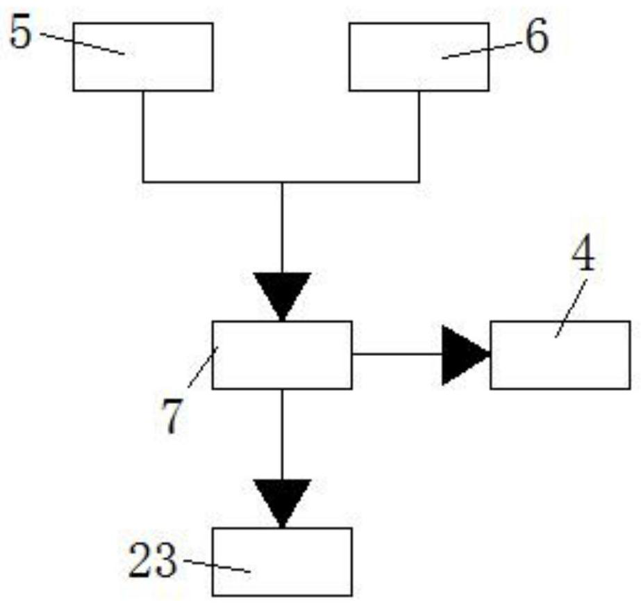
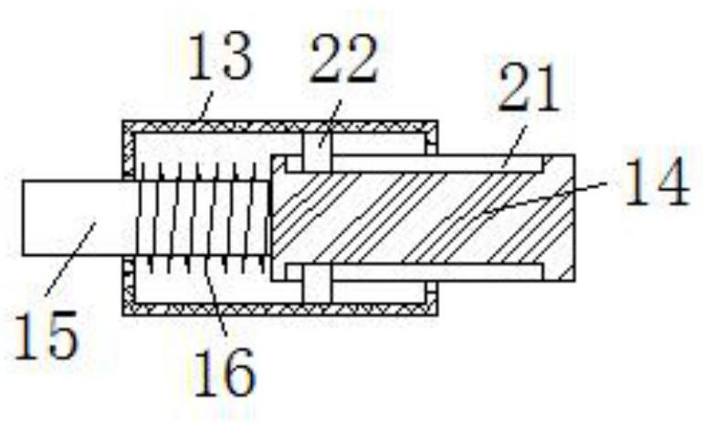
The invention discloses a use method of an automatic drainage system for water conservancy project construction. The automatic drainage system comprises a filtering pool, wherein the left side of thefiltering pool communicates with a drainage pipe, the end, away from the filtering pool, of the drainage pipe communicates with a buffer pool, the other side of the buffer pool communicates with a water pump body, a flow sensor is arranged on the surface of the drainage pipe, an inner cavity of the buffer pool is fixedly connected with a water level sensor, and the top of the buffer pool is fixedly connected with a PLC. Water entering the filtering pool is filtered through an impurity filtering net in the inner cavity of the filtering pool, the filtered water is guided to the buffer pool through the drainage pipe, the anti-backflow baffle in the inner cavity of the buffer pool can rise under the buoyancy effect of the water, and therefore the water can continue to flow leftwards, the waterpump body discharges and sucks the water, and the problems that an existing drainage system is clogged in the drainage process, clogging is unlikely to be found, the clogging can cause power increaseof a pump machine, and even the pump machine is damaged are solved.

Description

technical field [0001] The invention relates to the technical field of hydraulic engineering, in particular to a method for using an automatic drainage system for hydraulic engineering construction. Background technique [0002] Water conservancy project is a general term for various engineering constructions built to control, utilize and protect surface and underground water resources and the environment, including flood control, waterlogging, irrigation, power generation, water supply, reclamation, water and soil conservation, immigration and water resource protection, etc. Projects, including new construction, expansion, reconstruction, reinforcement, restoration and their supporting and ancillary projects, are used to control and allocate natural surface water and groundwater to achieve the purpose of removing harm and promoting benefits, also known as water conservancy projects. In the construction of water conservancy projects, construction is often carried out in plac...

Claims


Application Information

Patent Timeline
Patent Type & Authority Applications(China)
IPC IPC(8): E03F5/14E03F5/22F04D15/02
CPCE03F5/14E03F5/22E03F2201/20E03F2201/30F04D15/0209
Inventor 任蕾朱娇飞邵徐亮
Owner 山东润康水务有限公司
Why Eureka
Try Eureka