Program-controlled coal discharging device for raw coal bunker

A technology of bunker program control and raw coal bunker, which is applied in the field of coal equipment under program control of raw coal bunker, can solve problems such as affecting production and unsmooth feeding of raw coal, and achieves the effects of convenient installation, high degree of coal injection automation and strong practicability.

Active Publication Date: 2013-12-04
MCC CAPITAL ENGINEERING & RESEARCH
View PDF7 Cites 10 Cited by
  • Summary
  • Abstract
  • Description
  • Claims
  • Application Information

AI Technical Summary

Problems solved by technology

[0007] The purpose of the present invention is to provide a program-controlled coal unloading device for raw coal bunkers to solve the problem in the prior art that unsmooth unloading of raw coal in the raw coal bunker affects production

Method used


Image

  • Program-controlled coal discharging device for raw coal bunker
  • Program-controlled coal discharging device for raw coal bunker
  • Program-controlled coal discharging device for raw coal bunker

Examples


Embodiment 1

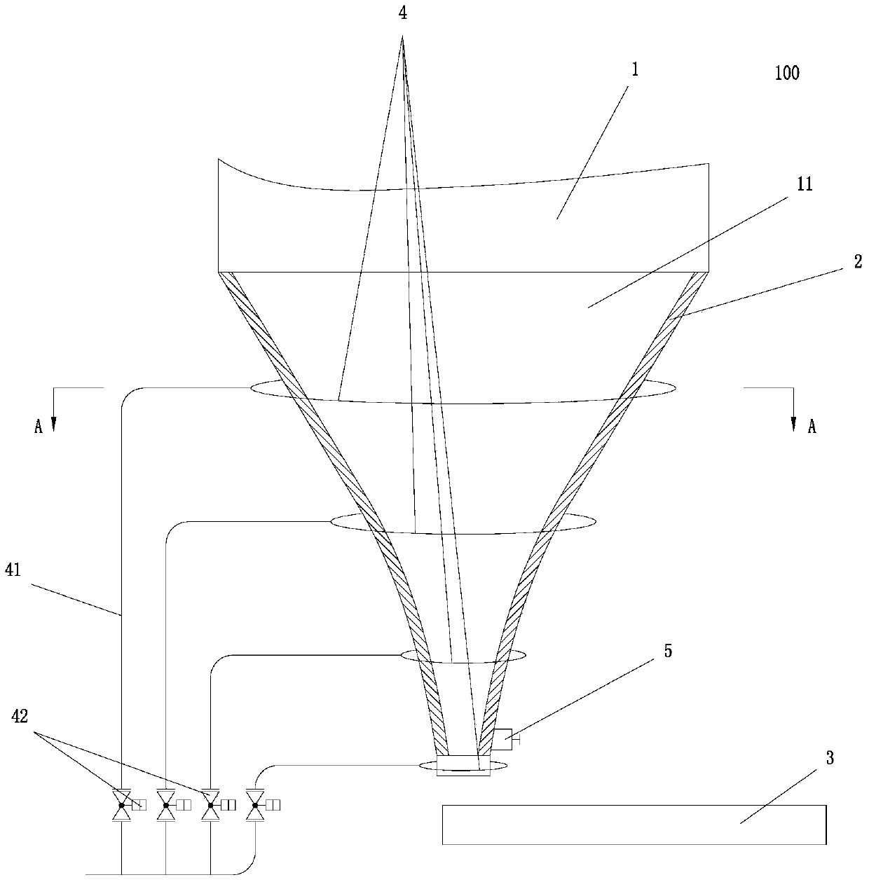
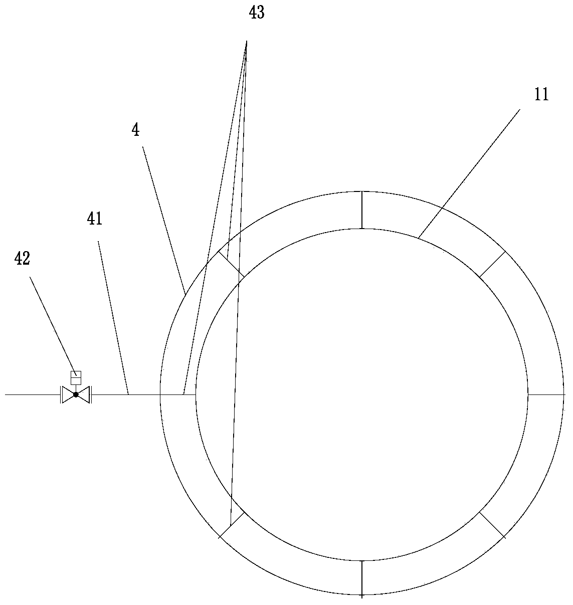
[0021] Such as figure 1 , figure 2 As shown, the present invention proposes a program-controlled coal lowering device 100 for raw coal bunkers. The raw coal bunker program-controlled coal lowering device 100 includes a raw coal bunker 1 with a tapered section 11 at the bottom, and a smooth liner is laid on the inner wall of the tapered section 11. 2. A coal feeder 3 is correspondingly provided below the discharge port at the bottom of the conical section 11; a plurality of hot nitrogen purging pipes 4 are provided on the outer wall of the conical section 11 from top to bottom, and each of the hot nitrogen The nitrogen purge pipeline 4 is welded on the outer wall of the tapered section 11 through angle steel; each hot nitrogen purge pipeline 4 is connected to the coal injection station by the corresponding first pipeline 41 and the first control valve 42 provided in the first pipeline 41. Hot nitrogen output piping (not shown), such as figure 2 As shown, each hot nitrogen p...

Embodiment 2

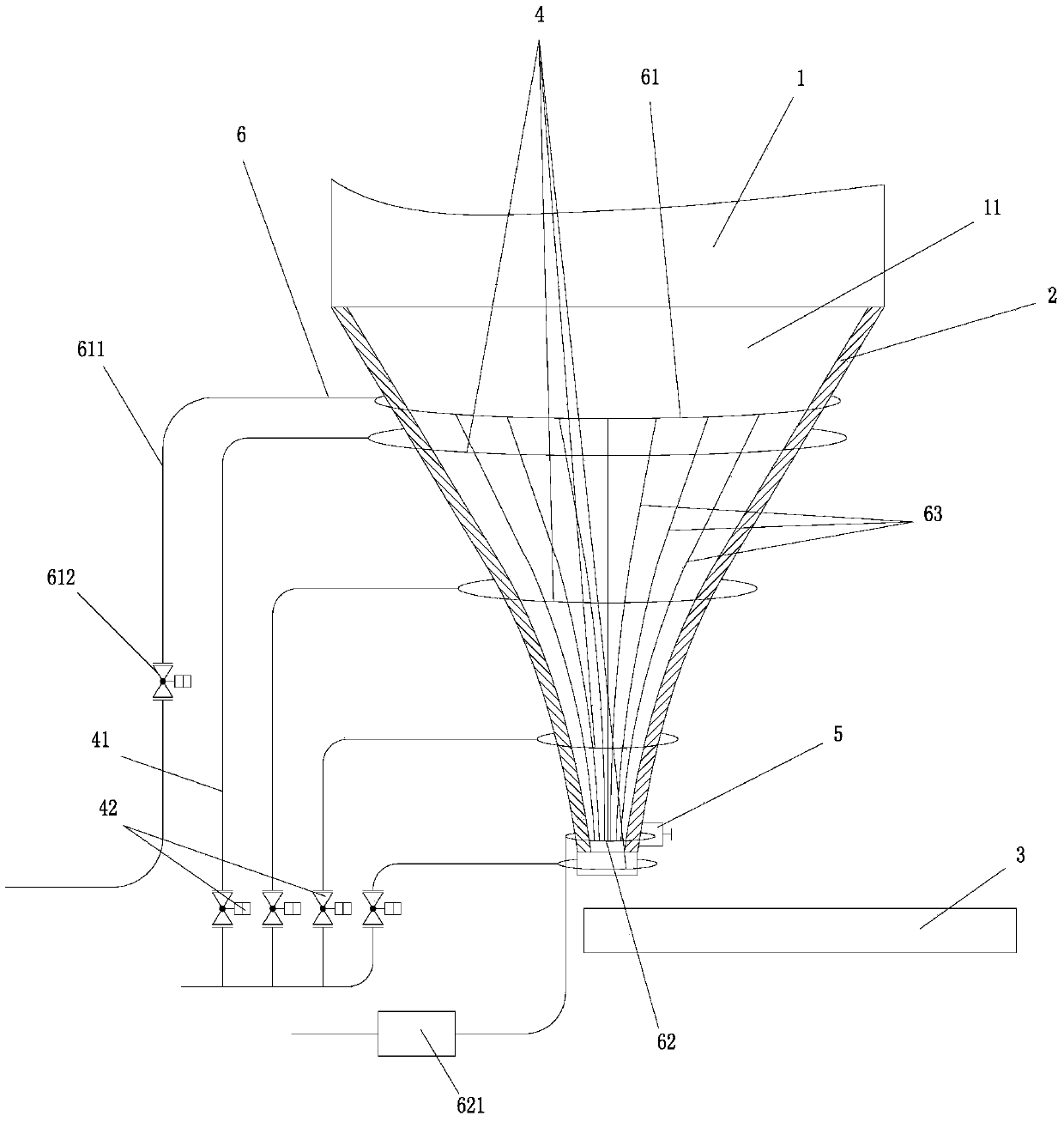
[0025] The structure and principle of this embodiment and the first embodiment are basically the same, and the difference between it and the first embodiment is that, as image 3 As shown, a steam tracing pipe 6 is arranged between the outer wall of the tapered section 11 and a plurality of hot nitrogen purge pipes 4, and the steam tracing pipe 6 is arranged close to the outer wall of the tapered section 11; The hot pipe 6 includes an upper annular duct 61 arranged at the upper end of the conical section 11 and a lower annular duct 62 arranged at the outlet of the tapered section, between the upper annular duct 61 and the lower annular duct 62 and around the The outer wall of the tapered section 11 is longitudinally spaced with a plurality of connecting pipes 63, and the two ends of each connecting pipe 63 are connected to the upper annular pipe 61 and the lower annular pipe 62 respectively; the upper annular pipe 61 is formed by the second pipeline 611 and the second control ...


PUM


Abstract

The invention relates to a program-controlled coal discharging device for a raw coal bunker. The program-controlled coal discharging device comprises a raw coal bunker of which the lower part is of a conical section; a smooth lining plate is paved on the inner wall of the conical section; a coal feeder is correspondingly arranged below a discharge opening of the bottom end of the conical section; a plurality of hot nitrogen gas purging pipelines are arranged on the outer wall of the conical section at intervals from top to bottom; each hot nitrogen gas purging pipeline is formed by connecting a corresponding first pipeline and a first control valve arranged in the first pipeline to a hot nitrogen gas output pipeline of a coal injection station; a plurality of injection pipes are arranged around the circumference of the conical section of the outer wall of the conical section at intervals on each hot nitrogen gas purging pipeline; each injection pipe penetrates through the outer wall of the conical section and the lining plate and is conducted with the inside of the conical section; a quick-open hand hole is formed in the discharge opening of the bottom end of the conical section; a monitoring device for monitoring the flowing state of pulverized coal is arranged on the raw coal bunker; the monitoring device is electrically connected with a PLC (Program Logic Controller) automatic control device; when the discharging is unsmooth, the PLC automatic control device automatically controls valves of the hot nitrogen gas purging pipelines to be opened for purging the inside of the raw coal bunker to enable raw coal to be smoothly discharged.

Description

technical field [0001] The invention relates to an auxiliary equipment for ironmaking and coal injection, in particular to an intelligent coal bunker program-controlled coal loading device for smooth coal loading. Background technique [0002] Blast furnace coal injection is the most direct and effective method for ironmaking production to reduce costs, increase iron and save coke. The technological process of blast furnace coal injection is as follows: the raw coal enters the small raw coal bunker through a grab crane or forklift, and then the raw coal is transferred to the large raw coal bunker by the weighing device and the belt conveyor, and then the raw coal is transported to the medium-speed mill through the weighing device. The coal machine is milled, and the qualified coal powder is separated by the bag powder collector and transported to the coal powder warehouse for storage, and then the coal powder is sprayed to the blast furnace through the injection tank. The c...

Claims


Application Information

Patent Timeline
Patent Type & Authority Applications(China)
IPC IPC(8): B65D88/70
Inventor 陈伟刘佳宾王艳民叶果何锋锋赵志龙张波殷宝铎
Owner MCC CAPITAL ENGINEERING & RESEARCH
Why Eureka
Try Eureka