Fuel supply device and vehicle power system

A technology for fuel supply and vehicle power, which is applied in the field of liquefied gas fuel supply and can solve problems such as the absence of a fuel supply device

Pending Publication Date: 2020-10-30
SHANGHAI FUEL CELL VEHICLE POWERTRAIN
View PDF1 Cites 1 Cited by
  • Summary
  • Abstract
  • Description
  • Claims
  • Application Information

AI Technical Summary

Problems solved by technology

Among them, most of the existing research is to solve individual problems, and there is no integrated fuel supply device that can be applied to various environments

Method used


Image

  • Fuel supply device and vehicle power system

Examples


Embodiment 1

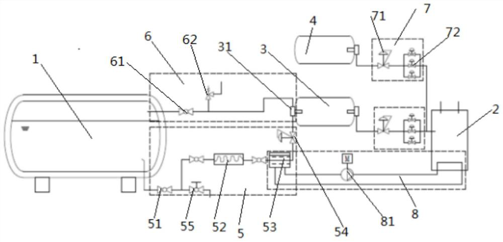
[0047] like figure 1 As shown, a fuel supply device is used to deliver the fuel in the liquefied gas storage tank 1 to the vehicle power module 2, including at least two fluid communication flow paths communicated with the low-pressure gas buffer module, and the low-pressure gas buffer module is connected to the vehicle Power module 2; wherein, the first fluid communication flow path 6 is used to receive the boil-off gas BOG (Boil-Off Gas, which refers to a low-temperature liquid that is pressurized and liquefied below its critical temperature, from the liquefied gas storage tank. Because it is difficult to be absolutely insulated from the environment, the gas that absorbs external heat and evaporates), the second fluid communication flow path 5 is used to receive the liquefied gas fuel from the liquefied gas storage tank 1 and heat it to form gasified gas; The flow path 5 is a heat exchange flow path for heat transfer. Connected to the low-pressure gas buffer module through ...

Embodiment 2

[0061] On the basis of Embodiment 1, this embodiment provides the application of the above-mentioned fuel supply device, which is not limited to the application on liquid fuel transport trucks. During the transportation process, the evaporated gas is stored and the stored low-pressure gas is used as a fuel for the truck. Transportation provides gaseous fuel. And it is widely used to provide gaseous fuel for various vehicles, including various vehicles that use fuel cells or natural gas engines as power sources.

[0062] Correspondingly, a vehicle power system with the fuel supply device provided in Embodiment 1 can be provided; specifically, it includes the fuel supply device and the vehicle power module 2, and the high-pressure gas storage module (including the high-pressure storage tank 4) in the fuel supply device ), the low-pressure gas buffer module (including the low-pressure buffer tank 3) provides gaseous fuel to the vehicle power module 2; and uses the second fluid co...


PUM


Abstract

The invention belongs to the technical field of liquefied gas fuel supply, and discloses a fuel supply device, which is used for conveying fuel in a liquefied gas storage tank to a vehicle power module. The fuel supply device comprises at least two fluid communication flow paths, a heat exchange flow path and a high-pressure gas storage module, wherein the at least two fluid communication flow paths communicate with a low-pressure gas slow storage module, and the low-pressure gas slow storage module is connected to the vehicle power module; the first fluid communication flow path is used for receiving boiloff gas (BOG) of the liquefied gas storage tank, and the second fluid communication flow path is used for receiving liquefied gas from the liquefied gas storage tank and heating the liquefied gas so as to be gasified; the heat exchange flow path is used for heat transfer with the second fluid communication flow path; and the high-pressure gas storage module is used for supplying high-pressure gas fuel to the vehicle power module. The fuel supply device is integrated and can be applied in various environments. Additionally, the invention further provides the vehicle power system. The vehicle power system comprises the fuel supply device, and the application range is wide.

Description

technical field [0001] The invention belongs to the technical field of liquefied gas fuel supply, in particular to a fuel supply device and a vehicle power system. Background technique [0002] Throughout the history of human energy evolution over the past hundred years, it is essentially a history of adjustment of the carbon-hydrogen ratio. The hydrogen content has been continuously increased, and the energy density has also been continuously increased. So far, there have been two energy revolutions in human history. In the first energy revolution, coal replaced wood as the dominant energy source, and in the second energy revolution, oil replaced coal as the dominant energy source. Although fossil energy is still dominant at present, considering the increasingly prominent shortage of fossil energy resources, the environmental pollution caused by vehicle emissions and the depletion of oil resources are increasing day by day, finding clean alternative energy is a problem tha...

Claims


Application Information

Patent Timeline
Patent Type & Authority Applications(China)
IPC IPC(8): F02M21/02H01M8/04007H01M8/04014H01M8/04029H01M8/04082H01M8/04089B60L58/33B60K11/02
CPCB60K11/02B60L58/33F02M21/0215F02M21/0221F02M21/023H01M8/04014H01M8/04029H01M8/04074H01M8/04089H01M8/04208Y02E60/50Y02T10/30Y02T90/16Y02T90/40
Inventor 李仕栋杨雪林吴兵
Owner SHANGHAI FUEL CELL VEHICLE POWERTRAIN
Why Eureka
Try Eureka