
Lifting protection device for security and protection monitoring camera

A technology for security monitoring and protection devices, applied in fluid pressure actuation devices, cleaning methods using tools, closed-circuit television systems, etc., can solve the problems of poor protection of protection devices against rain, reduced camera field of view, and dead angles

Inactive Publication Date: 2020-10-30
安徽科易果网络科技有限公司
View PDF5 Cites 6 Cited by
  • Summary
  • Abstract
  • Description
  • Claims
  • Application Information

AI Technical Summary

Problems solved by technology

[0005] Aiming at the deficiencies of the prior art, the present invention provides a security monitoring camera lifting protection device, which is equipped with a fast lifting camera, improves the field of view of the camera, protects the camera, has the advantage of automatically cleaning the lens, and solves the problem that the protection device will cover the camera. The lens part reduces the field of view of the camera, resulting in dead angles. In addition, the existing protective device has poor protection against rainwater. When rainwater contaminates the lens, it is easy to pollute the lens, thereby reducing the clarity of the camera.

Method used


Image

  • Lifting protection device for security and protection monitoring camera
  • Lifting protection device for security and protection monitoring camera
  • Lifting protection device for security and protection monitoring camera

Examples


Embodiment Construction

[0025] The technical solutions in the embodiments of the present invention will be clearly and completely described below in conjunction with the accompanying drawings in the embodiments of the present invention. Obviously, the described embodiments are only a part of the embodiments of the present invention, rather than all the embodiments. Based on the embodiments of the present invention, all other embodiments obtained by those of ordinary skill in the art without creative work shall fall within the protection scope of the present invention.

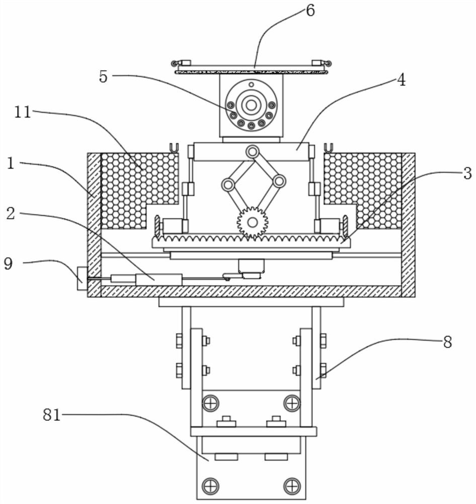
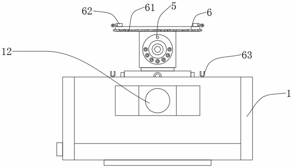
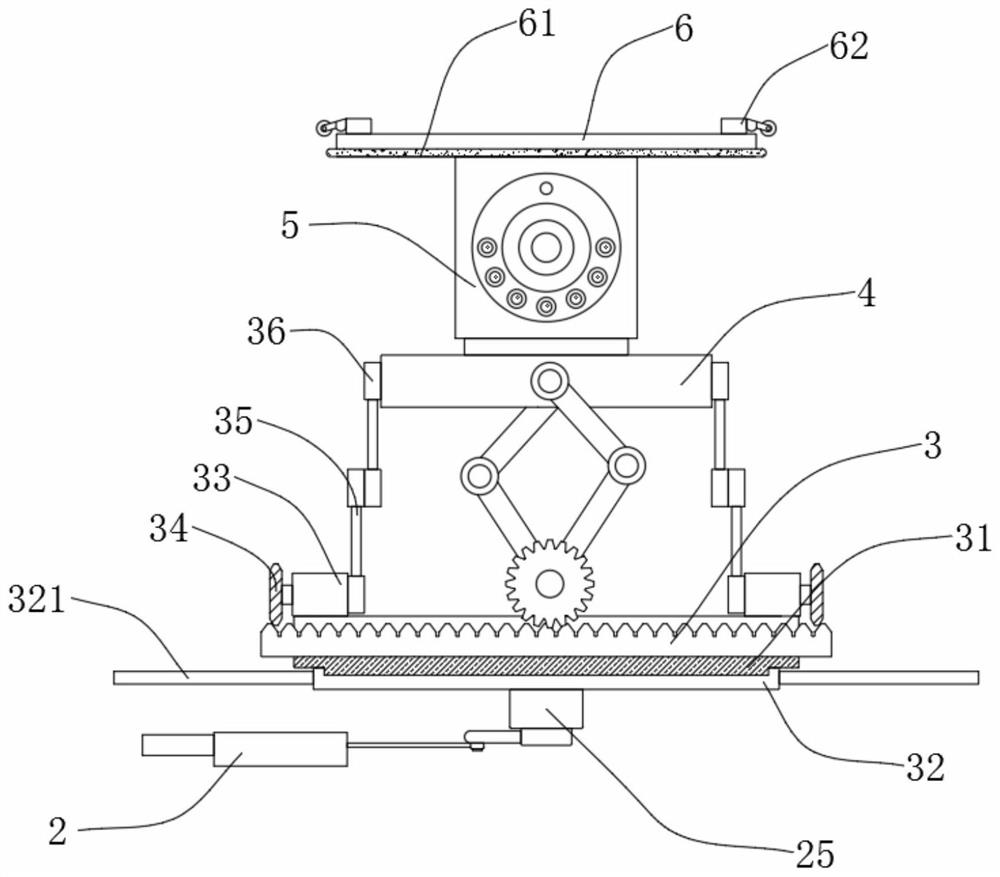
[0026] See Figure 1-6 , A security surveillance camera lifting protection device, including a protective shell 1, the inner side wall of the protective shell 1 is fixedly connected with a sponge buffer layer 11, the outer side wall of the protective shell 1 is fixedly connected with a riot glass sheet 12, the sponge buffer layer 11 has a good Anti-vibration buffering, so that the sponge buffer layer 11 protects the internal camera 5, th...


PUM


Abstract

The invention relates to the technical field of security and protection monitoring equipment, and discloses a lifting protection device for a security and protection monitoring camera. The lifting protection device comprises a protection shell, a sliding rail is fixedly connected to the bottom end of the interior of the protection shell, a sliding block is slidably connected to the inner side wallof the sliding rail, and a driving end is fixedly connected to one end of the sliding rail; and the stretchable end of the driving end is fixedly connected with one side of the sliding block, a firstconnecting rod is fixedly connected to the top of the sliding block, and a second connecting rod is hinged to one end of the first connecting rod. The camera is fixed to a lifting plate, and when theexternal temperature is too high, alcohol liquid in a detection device is heated and volatilized to generate expansion gas, so that the expansion gas provides power for the driving end, the driving end drives the sliding block to slide, and the driving end drives an end face disc teeth to rotate; and the lifting mechanism is not provided with a track, so that the lifting speed is only influencedby the rotating speed of the end face disc teeth, the lifting plate can instantly lower the camera to the interior of the protection shell to protect the camera.

Description

Technical field [0001] The invention relates to the technical field of security monitoring equipment, in particular to a lifting protection device for a security monitoring camera. Background technique [0002] The security monitoring system uses optical fiber, coaxial cable or microwave to transmit video signals in its closed loop, and constitutes an independent and complete system from camera to image display and recording. It can reflect the monitored object in real time, vividly, and truthfully. It not only greatly extends the observation distance of the human eye, but also expands the function of the human eye. It can replace manual long-term surveillance in harsh environments, allowing people to see Everything that actually happened to the monitored site was recorded by a video recorder. At the same time, the alarm system equipment alarms for illegal intrusion, and the generated alarm signal is input to the alarm host, and the alarm host triggers the monitoring system to r...

Claims


Application Information

Patent Timeline
IPC IPC(8): F16M11/04F16M11/18F16M13/02F15B15/06F15B21/06B08B1/02H04N7/18
CPCF16M11/046F16M11/18F16M13/02F15B15/065F15B21/06H04N7/18F15B2015/208B08B1/12B08B1/20
Inventor 陈琛
Owner 安徽科易果网络科技有限公司
Learn More