Three-dimensional scanning device

A three-dimensional scanning and cavity technology, applied in the field of three-dimensional scanning, can solve the problems of increased workload of staff, insufficient uniformity and inconvenience of scanning points, and achieves convenient scanning, comprehensive scanning points, and accurate scanning results. Effect

Active Publication Date: 2020-10-30
CHONGQING INST OF ENG
View PDF5 Cites 6 Cited by
  • Summary
  • Abstract
  • Description
  • Claims
  • Application Information

AI Technical Summary

Problems solved by technology

[0004] 1. The scanning method of the handheld scanner increases the workload of the staff. At the same time, the movement of the handheld scanner during the scanning work will cause the local scanning points to be uneven due to the irregularity and unevenness of the staff's hand-held movement. , so that the point data is not accurate enough;
[0005] 2. The fixed position scanner scans the object by rotating the electric turntable. Although the scanning is uniform, when scanning the bottom of the workpiece, it needs to be turned over manually, which is not convenient enough, and the position of the scanner cannot be adjusted;

Method used


Image

  • Three-dimensional scanning device
  • Three-dimensional scanning device
  • Three-dimensional scanning device

Examples


Embodiment Construction

[0028] In order to enable those skilled in the art to better understand the present invention, the technical solution of the present invention will be further described below in conjunction with the accompanying drawings and embodiments.

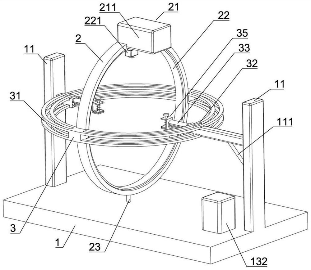
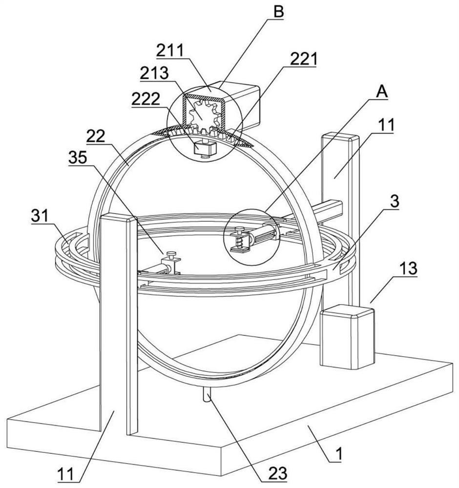
[0029] Such as Figure 1-Figure 5As shown, a three-dimensional scanning device of the present invention includes a base 1, an inner ring mechanism 2 and an outer ring mechanism 3 are arranged on the upper side of the base 1, and the inner ring mechanism 2 and the outer ring mechanism 3 are arranged in a cross shape and are fixedly connected to each other , the inner ring mechanism 2 is provided with a first rotating assembly 21 and an annular rotating plate 22 rotationally connected with the inner ring mechanism 2, the first rotating assembly 21 includes a first casing 211, and a first motor 212 is arranged inside the first casing 211, The output shaft of the first motor 212 is provided with a first gear 213, and the outer side of the annula...


PUM


Abstract

The invention belongs to the technical field of three-dimensional scanning, and particularly relates to a three-dimensional scanning device. The three-dimensional scanning device comprises a base, wherein the base is provided with an inner ring mechanism and an outer ring mechanism; the inner ring mechanism is provided with a first rotating assembly and an annular rotating plate; the first rotating assembly comprises a first case; the first case is provided with a first motor; the first motor is provided with a first gear; the annular rotating plate is provided with rotating teeth; the annularrotating plate is provided with a scanning camera; the inner ring mechanism is provided with a rotating rod; the outer ring mechanism is provided with a cross ring groove; the cross ring groove is connected with a cross sliding block in a sliding manner; the base is provided with a supporting column; the cross sliding block is provided with a clamping jaw mechanism; a cavity is formed in the base; the base is provided with a second rotating assembly; the second rotating assembly comprises a straight rack and a second case; the rotating rod is connected with a second gear; the cavity is provided with a positioning groove; the straight rack is provided with a hinging seat; the hinging seat is hinged to a hinging rod; a second motor is arranged in the second case; the second motor is connected with a rotating disc; the rotating disc is provided with a connecting rod; and the connecting rod is hinged to the hinging rod.

Description

technical field [0001] The invention belongs to the technical field of three-dimensional scanning, and in particular relates to a three-dimensional scanning device. Background technique [0002] A 3D scanner is a scientific instrument used to detect and analyze the shape and appearance data of objects or environments in the real world. By creating a point cloud of the geometric surface of the object, the collected data is used for 3D reconstruction calculations (the more intensive point cloud can create a more accurate model). These models have a wide range of uses, such as industrial design, defect detection, reverse engineering, robot guidance, landform measurement, medical information, biological information, criminal identification, digital cultural relic collection, film production, game creation materials, etc. application. [0003] Due to the limited scanning range of the three-dimensional scanner, the existing three-dimensional scanning device usually uses a hand-h...

Claims


Application Information

Patent Timeline
Patent Type & Authority Applications(China)
IPC IPC(8): F16M11/04F16M11/12F16M11/18F16M11/22G01B11/24
CPCF16M11/04F16M11/12F16M11/18F16M11/22G01B11/24
Inventor 周亮李静
Owner CHONGQING INST OF ENG
Why Eureka
Try Eureka