Transformer fault detection method and box-type transformer
A technology for transformer faults and detection methods, applied in the field of transformers, can solve the problems of inability to specifically determine the specific location of the fault type, inability to effectively determine the severity of the fault, and detection of a single transformer fault, so as to improve the maintenance management efficiency and facilitate maintenance and replacement. , the effect of reducing workload
- Summary
- Abstract
- Description
- Claims
- Application Information
AI Technical Summary
Problems solved by technology
Method used
Image
Examples
Embodiment 1
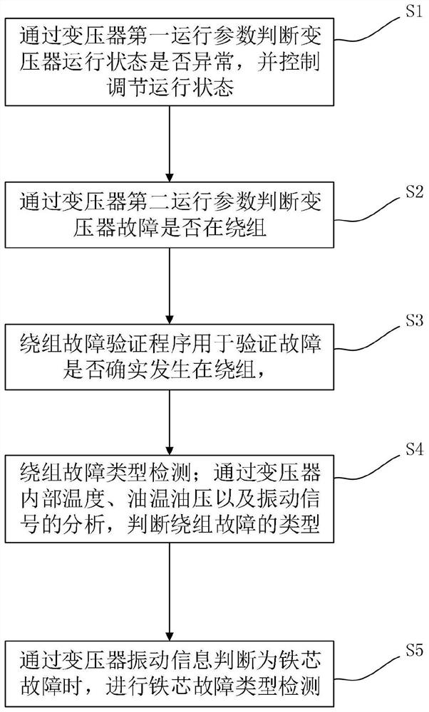
[0054] Such as figure 1 As shown, it is a flow chart of the transformer fault detection method provided by the embodiment of the present invention. In this embodiment, the transformer fault detection method is based on a predetermined fault value range and a normal value range to judge whether the transformer under test is faulty, and specifically includes the following process:
[0055] Step S1: Judging whether the transformer running state is abnormal according to the first transformer running parameter, and controlling and adjusting the running state.
[0056] Wherein the first operating parameter includes the internal temperature of the transformer, output current and / or output voltage.
[0057] First, after the transformer has been running for a period of time, it starts to detect the various operating parameters of the transformer. Due to the limitation of the internal structure of the transformer, heat will be generated inside the transformer after it starts running, ca...
Embodiment 2
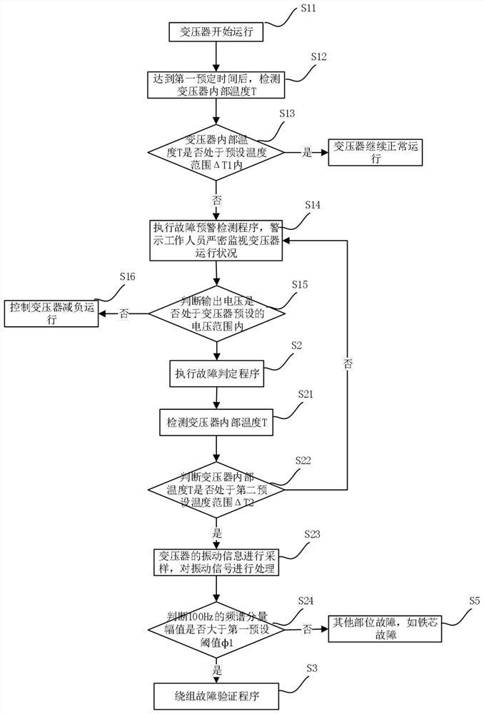
[0074] On the basis of Embodiment 1, this embodiment further limits the transformer fault detection method. Specifically, it includes the following processes:
[0075] Step S11: Start the transformer to start running.
[0076] Step S12: After the running time of the transformer reaches the first predetermined time, the detection device starts to detect the internal temperature T of the transformer.
[0077] Wherein the first predetermined time is determined according to the time from when the transformer is turned on to when it reaches a stable running state. When the running time of the transformer is less than the first predetermined time, the transformer has not yet entered the normal running state, and the detected internal temperature of the transformer is low, which affects the judgment result. Therefore, after the operating time of the transformer reaches the first predetermined time, the internal temperature of the transformer must be detected through the temperature...
Embodiment 3
[0113] As an embodiment of the present invention, this embodiment also provides a box-type transformer fault detection system. The transformer includes a box body, a transformer body and a detection system. The transformer body includes a transformer winding, a transformer core and a cooling device, and cooling oil is stored in the cooling device. For box-type transformers with larger iron cores, in order to facilitate heat dissipation inside the iron core and fully reduce eddy current losses, etc., the cooling device is installed between the silicon steel sheet laminations that make up the iron core, and the iron core is divided into several parts by the cooling device. Core frame. During the lamination process of the transformer core, the silicon steel sheets on both sides of the cooling device may be short-circuited, resulting in a short circuit between the core frames.
[0114] The detection system includes a control device, an analysis module, a timer and a detection dev...
PUM
 Abstract
Description
Claims
Application Information
 - R&D
- Intellectual Property
- Life Sciences
- Materials
- Tech Scout
- Unparalleled Data Quality
- Higher Quality Content
- 60% Fewer Hallucinations
Browse by: Latest US Patents, China's latest patents, Technical Efficacy Thesaurus, Application Domain, Technology Topic, Popular Technical Reports.
© 2025 PatSnap. All rights reserved.Legal|Privacy policy|Modern Slavery Act Transparency Statement|Sitemap|About US| Contact US: help@patsnap.com


