Supercharge Your Innovation With Domain-Expert AI Agents!

Winding machine and method for full-automatic take-up and pay-off

A technology of winding and unwinding machines, applied in coil manufacturing, electrical components, inductance/transformer/magnet manufacturing, etc., which can solve problems such as error-prone, low product production efficiency, and single production line, so as to avoid breakage and improve winding The effect of high line quality and accuracy

Pending Publication Date: 2020-10-30
WUHAN INSTITUTE OF TECHNOLOGY
View PDF0 Cites 0 Cited by
  • Summary
  • Abstract
  • Description
  • Claims
  • Application Information

AI Technical Summary

Problems solved by technology

However, most of the winding machines currently put into the market are semi-automatic winding machines, and the participation of workers is very high. There is interference between the wires and the insulation layer is broken or the distance between the wires is too large to make the inductance coil irregular
Moreover, the manual winding process is prone to errors even for skilled workers. In addition, because the scope of use of the coil is different from the work requirements, the specifications and requirements of the coil produced by the winding machine are also different. Participating factors, the processing efficiency of the winding machine is low, and the existing winding mechanisms generally have fixed production specifications, so it is necessary to choose different winding machines according to different winding specifications and winding requirements. Production, therefore, is not only not versatile, but also when there are too many products in demand, the present invention will also cause the product production efficiency to be too low because the production line is too single, which is not conducive to saving production costs for winding machine manufacturers. It is also unable to meet the requirements of coil manufacturers for the use of winding machines.

Method used


Image

  • Winding machine and method for full-automatic take-up and pay-off
  • Winding machine and method for full-automatic take-up and pay-off
  • Winding machine and method for full-automatic take-up and pay-off

Examples


Embodiment Construction

[0021] In order to better understand the present invention, the present invention will be further described below in conjunction with the accompanying drawings and embodiments.

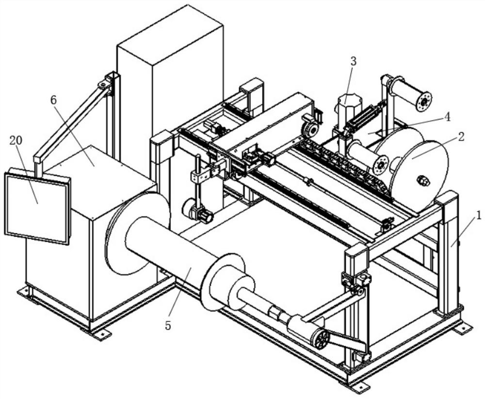
[0022] Such as figure 1 As shown, a fully automatic wire winding machine includes a base 1, a wire releasing device, a wire arranging device, a winding device and a control system. On the left and right sides, the cable arrangement device includes a main cable arrangement mechanism and an auxiliary cable arrangement mechanism. The system is respectively connected with the pay-off device, the cable arrangement device and the winding device to control the precise winding.

[0023] The pay-off device includes a pay-off cylinder 2, a pay-off motor 3 and a pay-off translation mechanism, and the pay-off translation mechanism includes a pay-off translation screw, a pay-off translation slide rail, a pay-off translation slider 4 and a pay-off translation motor arranged in parallel. , the pay-off translation ...


PUM


Abstract

The invention provides a winding machine and method for full-automatic take-up and pay-off. The winding machine comprises a base, a pay-off device, a winding displacement device, a winding device anda control system, wherein the pay-off device and the winding device are fixedly arranged on the left side and the right side of the base respectively, the wire arranging device comprises a main wire arranging mechanism and an auxiliary wire arranging mechanism, the main wire arranging mechanism is arranged at the top of the base, the auxiliary wire arranging mechanism is arranged on the wire preventing device and corresponds to a pay-off end, and the control system is connected with the pay-off device, the wire arranging device and the winding device and controls accurate winding. The windingmachine is more compact in structure, higher in product production efficiency and quality and high in automation degree.

Description

technical field [0001] The invention belongs to the technical field of winding machines for producing transformer coils, and in particular relates to a winding machine and method for fully automatic winding and unwinding. Background technique [0002] A winding machine is a device that winds a wire-like object onto a specific workpiece, and is usually used for coil winding. Transformer coils wound by enameled wires are generally used in electrical products. The winding machine is used to complete the entire process of winding the enameled wires on the barrel, and the winding mechanism is an indispensable part of the winding machine. At the same time, the higher the efficiency of the winding mechanism, the higher the production efficiency. However, most of the winding machines currently put into the market are semi-automatic winding machines, and the participation of workers is very high. Interference occurs between the wires and the insulation layer is scratched, or the di...

Claims


Application Information

Patent Timeline
IPC IPC(8): H01F41/06H01F41/082H01F41/096
CPCH01F41/06H01F41/082H01F41/096
Inventor 徐文霞于宝成罗建张敏艾玉明梁昊宁王志成李辉王春梅郭然张丽娜
Owner WUHAN INSTITUTE OF TECHNOLOGY
Features
  • R&D
  • Intellectual Property
  • Life Sciences
  • Materials
  • Tech Scout
  • Unparalleled Data Quality
  • Higher Quality Content
  • 60% Fewer Hallucinations
Learn More