Transformer winding device

A technology of winding device and transformer, which is applied in inductance/transformer/magnet manufacturing, coil manufacturing, electrical components, etc., can solve the problems of wasting the internal space of the transformer, affecting the quality of the transformer, and the winding of the transformer is not tight.

Inactive Publication Date: 2020-10-30
顾亚花
View PDF0 Cites 0 Cited by
  • Summary
  • Abstract
  • Description
  • Claims
  • Application Information

AI Technical Summary

Problems solved by technology

The main functions are: voltage transformation, current transformation, impedance transformation, isolation, voltage stabilization, etc., so the coil is the main part of the transformer, and the coupling principle is used to transform the voltage, but the coil inside the conventional transformer is unstable due to the winding machine. The reason is that the winding of the transformer is not tight, which affects the quality of the transformer and wastes the internal space of the transformer.

Method used


Image

  • Transformer winding device
  • Transformer winding device
  • Transformer winding device

Examples


Embodiment 1

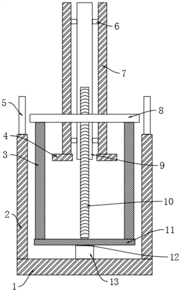
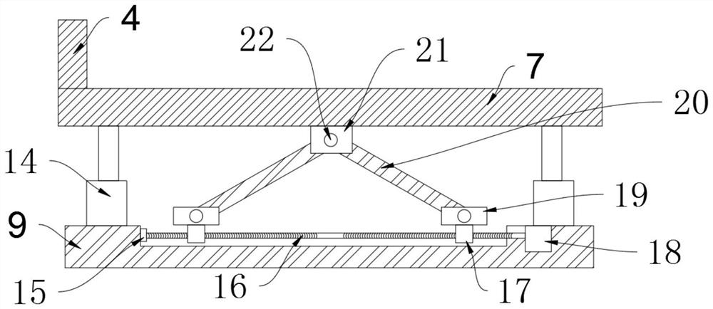
[0020] see Figure 1-4 , a transformer winding device, including a base 1, a side support rod 2 and a winding structure, the side support rod 2 is fixed on the side of the base 1, a winding structure is fixed above the base 1, and the winding structure The wire structure includes a bottom motor 13, a rotating shaft 12, a fixed turntable 11, a screw rod 10, a fixed seat 3, a winding mechanism, a built-in threaded sleeve 9, a clamping plate 7 and a support structure 6, and a bottom is fixed at the middle position above the base 1. Motor 13, the bottom motor 13 drives and connects the rotating shaft 12, the middle of the rotating shaft 12 is fixed with a fixed turntable 11, the rotating shaft 12 passes through the fixed turntable 11 and the end of the rotating shaft 12 is fixed with a screw 10, the screw 10 is threadedly connected to the built-in threaded sleeve 9, the built-in threaded sleeve 9 is externally fixed with a support structure 6, the end of the support structure 6 is...

Embodiment 2

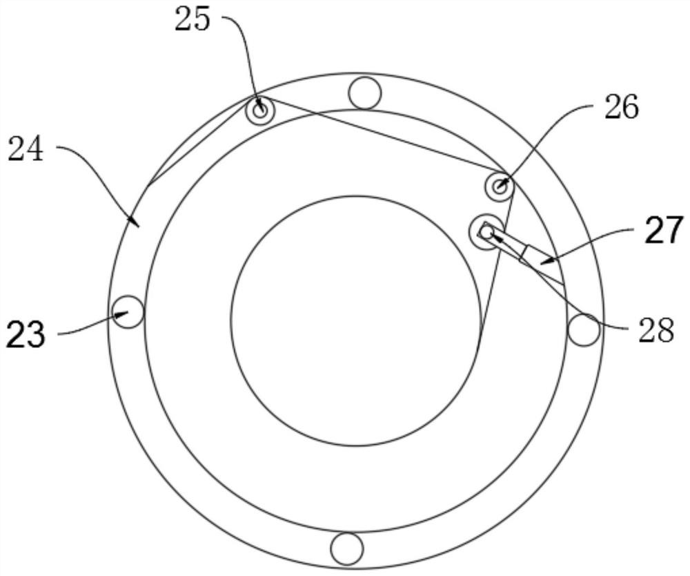
[0027] Compared with Embodiment 1, the improvement of this embodiment is that: the pay-off roller 24 is fixed with an elastic adjustment structure, and the elastic adjustment structure includes a clamping telescopic rod 27 and an adjustment roller 28, and the clamping telescopic rod 27 is fixed inside the winding placement roller 8, and the end of the clamping telescopic rod 27 is rotated to be provided with an adjustment roller 28, and a pressure sensor is fixed on the adjustment roller 28. The cable passes through the adjustment roller 28, the pressure sensor is used to detect the pressure of the cable, and the action of clamping the telescopic rod 27 is used to drive the adjustment roller 28 to elongate or shorten, so that the tensile force of the cable is fixed, avoiding the tension caused by the rope being too loose or Too tight affects the quality of winding.

[0028] The working principle of the present invention is: first, use the bottom motor 13 to raise the built-in ...


PUM


Abstract

The invention discloses a transformer winding device. The winding device comprises a base, a side edge supporting rod and a winding structure. The winding structure comprises a bottom motor, a rotating shaft, a fixed turntable, a screw rod, a fixed seat, a winding mechanism, a built-in threaded sleeve, a clamping plate and a supporting structure; the winding mechanism comprises a winding placementroller, a pay-off roller fixing column, a pay-off roller, a guide roller and an internal guide roller; and the supporting structure comprises an internal motor, a sliding seat, a bidirectional screwrod, a bearing seat, a fixed block, a rotating rod, a top fixed seat and a rotating shaft. According to the device, winding and up-and-down movement are driven by the same motor, the drive can move upand down in the winding process, the winding is more uniform, gaps between cables are avoided, the quality of the cables is prevented from being affected, meanwhile, the limiting seat and the supporting structure are fixed to the device, a to-be-wound roller can be automatically fixed, and manpower is saved.

Description

technical field [0001] The invention relates to a transformer device, in particular to a transformer winding device. Background technique [0002] Transformer is a device that uses the principle of electromagnetic induction to change AC voltage. The main components are primary coil, secondary coil and iron core. The main functions are: voltage transformation, current transformation, impedance transformation, isolation, voltage stabilization, etc., so the coil is the main part of the transformer, and the coupling principle is used to transform the voltage, but the coil inside the conventional transformer is unstable due to the winding machine. The reason is that the winding of the transformer is not tight, which affects the quality of the transformer and wastes the internal space of the transformer. Contents of the invention [0003] The purpose of the present invention is to provide a transformer winding device to solve the problems raised in the background art above. ...

Claims


Application Information

Patent Timeline
Patent Type & Authority Applications(China)
IPC IPC(8): H01F41/06H01F41/082H01F41/094H01F41/096
CPCH01F41/06H01F41/082H01F41/094H01F41/096
Inventor 顾亚花
Owner 顾亚花
Why Eureka
Try Eureka