Probe detection system

A detection system and probe technology, which is applied in the field of probe microscopy, can solve problems such as inability to obtain accurate results and consider the transient mode of the cantilever, and achieve the effect of minimizing the transient effect and making the transient effect convenient

Active Publication Date: 2011-06-01
INFINITESIMA
View PDF10 Cites 29 Cited by
  • Summary
  • Abstract
  • Description
  • Claims
  • Application Information

AI Technical Summary

Problems solved by technology

This overcomes the problem of motion errors introduced by the scanner: the z-direction motion of the probe tip is caused solely by the shape of the sample surface
However, this prior art device, while capable of operating in the second speed mode, does not take into account the instantaneous mode of the boom
While providing better tracking, which correspondingly delays the onset of the third mode, this microscope still does not yield accurate results if operated in the third mode

Method used


Image

  • Probe detection system
  • Probe detection system
  • Probe detection system

Examples


Embodiment Construction

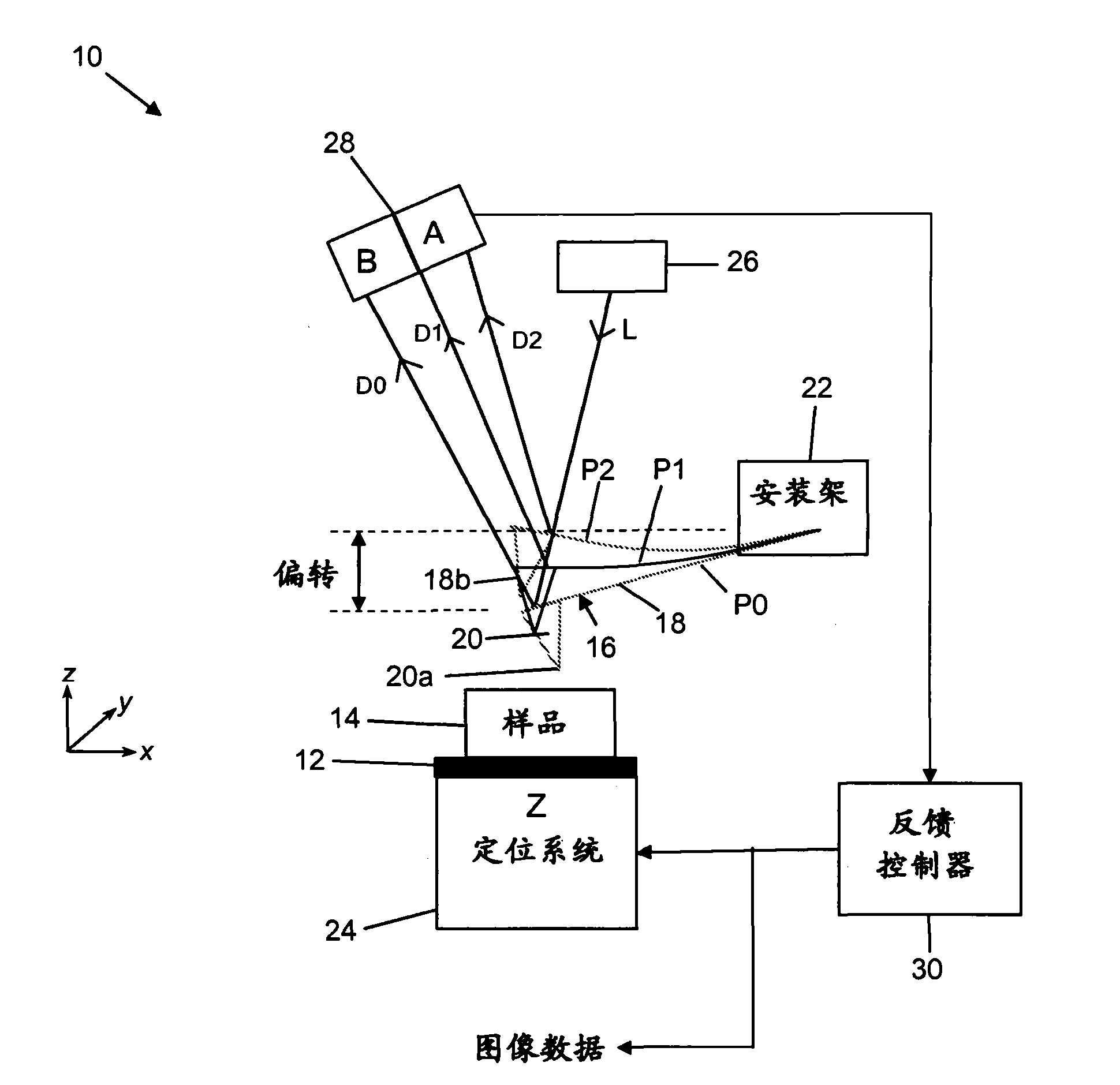
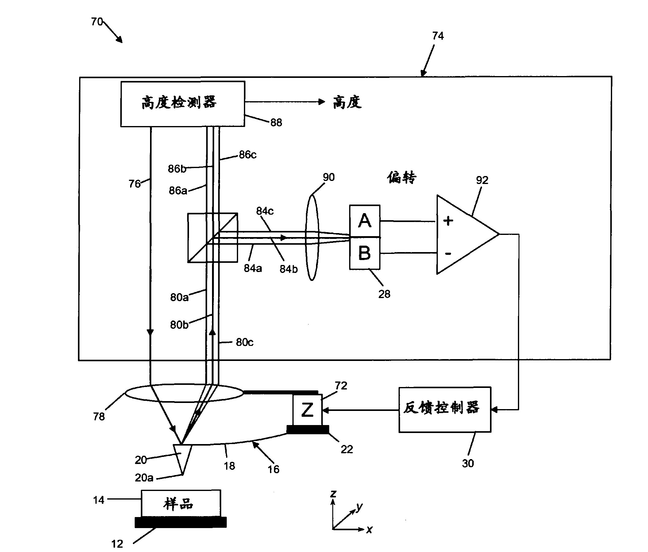
[0111] refer to image 3 , schematically illustrates an embodiment of an AFM, indicated generally at 70, utilizing a first embodiment of a detector constructed in accordance with an aspect of the invention. Elements in common with the prior art AFM described earlier with reference to FIG. 1 are given the same reference numerals. Accordingly, the illustrated AFM apparatus includes a movable stage 12 adapted to accommodate a sample 14 whose surface is to be inspected by a probe 16 . Probe 16 includes cantilever beam 18 and needle tip 20 that tapers toward point 20 a and is positioned toward one end of cantilever beam 18 . The other end of the cantilever beam 18 is supported by a mounting bracket 22 .

[0112] One or more drive motors (72, not shown) are used to drive the sample 14 (together with the stage 12) and / or the probe 16 so that they can be moved relative to each other in three dimensions, namely the x, y and z directions. scan each other. As is conventional in the a...


PUM


Abstract

A probe detection system (74) for use with a scanning probe microscope comprises both a height detection system (88) and deflection detection system (28). As a sample surface is scanned, light reflected from a microscopeprobe (16) is separated into two components. Afirstcomponent (84) is analysed by thedeflection detection system (28) and is used in a feedback systemthatmaintainsthe average probe deflection substantially constant during the scan. The second component (86) is analysed by the height detection system (88) from which an indication of the heightof the probe above a fixed reference point, and thereby an image of the sample surface, is obtained. Such a dual detection system is particularly suited for use in fast scanning applications in which thefeedback systemis unableto respond at the raterequired to adjust probe height betweenpixel positions.

Description

technical field [0001] The present invention relates to the field of probe microscopy and in particular to a detection system for monitoring the position of a microscope probe in relation to a sample surface. Background technique [0002] The principle behind scanning probe microscopy (SPM) is used to mechanically scan a nanoprobe tip over a sample surface to produce an image of the sample. Features within the image are derived from changes in the interaction between the tip and the sample. [0003] A specific example of SPM is atomic force microscopy (AFM), where the force interaction between the sample and the sharp tip of the probe is monitored. The probe of a typical AFM consists of a very small cantilever whose base is fixed to a support, with the tip at the opposite (free) end of the cantilever. When the probe tip is brought into close proximity to the sample, an interaction force is created between the sample and the tip. If the needle tip is in motion, eg oscillat...

Claims


Application Information

Patent Timeline
Patent Type & Authority Applications(China)
IPC IPC(8): G12B21/20G01N13/16G01B9/02G01Q10/06G01Q20/02
CPCB82Y35/00G01Q20/02G01Q10/065G01B2290/45G01B11/0608G01Q10/00G01Q60/24G01B9/02
Inventor 安德鲁·汉弗里斯
Owner INFINITESIMA
Why Eureka
Try Eureka