
Nozzle device and spraying equipment

A nozzle device and nozzle technology, applied in the direction of spray device, building, building structure, etc., can solve the problems of large size of nozzle device, inconvenient spraying operation, affecting spraying quality, etc., to achieve high spraying efficiency, good wall adaptability, The effect of improving spraying efficiency

Active Publication Date: 2021-11-16
GUANGDONG BOZHILIN ROBOT CO LTD
View PDF0 Cites 0 Cited by
  • Summary
  • Abstract
  • Description
  • Claims
  • Application Information

AI Technical Summary

Problems solved by technology

The robotic arm carries a single nozzle, which is suitable for spraying in narrow spaces, but the spraying efficiency is low
The robotic arm carries multiple nozzles for spraying operations. Although it can improve the spraying efficiency, the size of the nozzle device is large, which is suitable for spraying operations in large spaces. For spraying areas with limited space, it is not convenient for spraying operations and affects the quality of spraying.

Method used


Image

  • Nozzle device and spraying equipment
  • Nozzle device and spraying equipment
  • Nozzle device and spraying equipment

Examples


Embodiment 1

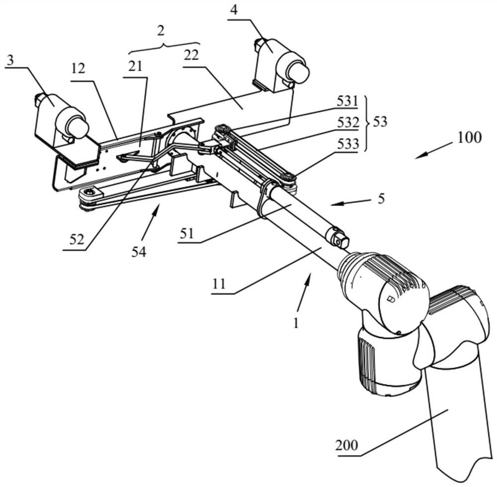
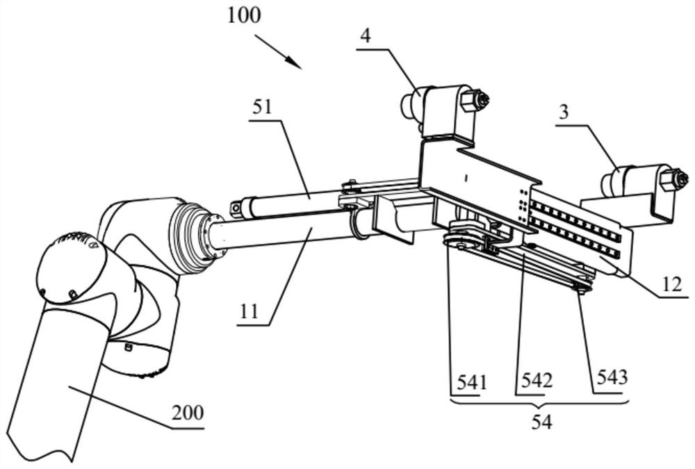
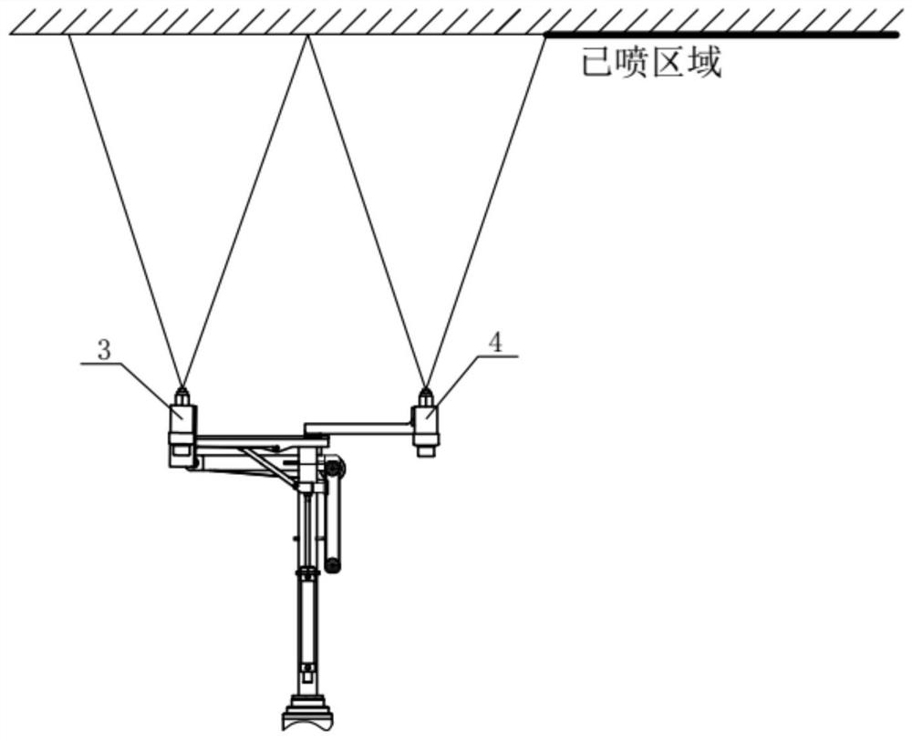
[0052] Such as Figure 1-Figure 9 As shown, this embodiment provides a nozzle device 100, including a mounting frame 1, a nozzle assembly and a driving mechanism 5, the nozzle assembly includes a fixed frame 2, a first nozzle 3 and a second nozzle 4, and the fixed frame 2 is movably arranged On the mounting frame 1, the first nozzle 3 and the second nozzle 4 are all arranged on the fixed frame 2; the driving mechanism 5 is arranged on the mounting frame 1, and the output end of the driving mechanism 5 is connected with the fixed frame 2 in transmission, and the driving mechanism 5 can Drive the fixed frame 2 to overlap and unfold the mounting frame 1, and make the spraying direction of the first nozzle 3 intersect with the spraying direction of the second nozzle 4 when the fixed frame 2 and the mounting frame 1 are in a stacked state; when the fixed frame 2 When the installation frame 1 is in the unfolded state, the spraying direction of the first nozzle 3 is the same as that ...

Embodiment 2

[0078] Such as Figure 10-Figure 11 As shown, this embodiment provides an optional nozzle device 100, which differs from Embodiment 1 in that:

[0079] The installation frame 1 only includes the first installation part 11 , does not include the second installation part 12 , and the driving mechanism 5 is installed on the first installation part 11 .

[0080] Further, the fixed frame 2 includes a rotary part 23 and a rotary part 24, the rotary part 23 is rotatably arranged on the mounting frame 1 (ie, the first mounting part 11), and the first nozzle 3 is arranged on the rotary part 23; the rotary part 24 Rotatably arranged on the rotating member 23, the second nozzle 4 is arranged on the rotating member 24; the driving mechanism 5 can drive the rotating member 23 to rotate relative to the mounting frame 1 and overlap with the mounting frame 1, and drive the rotating member 24 relative to the The rotating member 23 rotates so that the spraying direction of the second nozzle 4 ...


PUM


Abstract

The invention relates to the technical field of construction machinery, in particular to a nozzle device and spraying equipment. The nozzle device includes a mounting frame, a nozzle assembly and a driving mechanism, the nozzle assembly includes a fixed frame, a first nozzle and a second nozzle, the fixed frame is movably arranged on the mounting frame, and the first nozzle and the second nozzle are both arranged on a fixed on the frame; the driving mechanism is arranged on the mounting frame, and the output end of the driving mechanism is connected with the fixed frame through transmission. The spraying direction of the first nozzle intersects the spraying direction of the second nozzle; when the fixed frame and the installation frame are in the unfolded state, the spraying direction of the first nozzle is the same as that of the second nozzle. The nozzle device improves the spraying efficiency while improving the wall adaptability of the nozzle device, so that the spraying operation is more flexible.

Description

technical field [0001] The invention relates to the technical field of construction machinery, in particular to a nozzle device and spraying equipment. Background technique [0002] Spraying is an important link in the decoration process, and its quality directly affects the final appearance of the wall. The spraying operation has the following characteristics: first, the market demand is large; second, the production efficiency is low; third, the labor cost is high; fourth, the spraying quality is high; Intelligent. [0003] At present, most of the existing spraying equipment use multi-degree-of-freedom mechanical arms to carry nozzles to realize spraying operations at any position in space. The robot arm carries a single nozzle, which is suitable for spraying operations in narrow spaces, but the spraying efficiency is low. The robotic arm carries multiple nozzles for spraying operations. Although it can improve the spraying efficiency, the size of the nozzle device is l...

Claims


Application Information

Patent Timeline
Patent Type & Authority Patents(China)
IPC IPC(8): B05B13/02B05B13/04B05B15/62B05B15/68E04F21/08
CPCB05B13/0278B05B13/04B05B15/62B05B15/68E04F21/08
Inventor 熊会平修德敏阳凯许安鹏
Owner GUANGDONG BOZHILIN ROBOT CO LTD
Learn More