Thread residue collecting device for textile production

A technology for collecting devices and textiles, applied in cleaning methods and utensils, cleaning methods using gas flow, chemical instruments and methods, etc., can solve the problems of difficulty in cleaning, easy access to the inside of human mouth and nose equipment, damage, etc. range effect

Active Publication Date: 2020-11-03
江西省蒙恩纺织有限公司
View PDF23 Cites 0 Cited by
  • Summary
  • Abstract
  • Description
  • Claims
  • Application Information

AI Technical Summary

Problems solved by technology

[0003] In the process of textile production, many impurities such as thread ends and rags will be produced. These impurities are light in weight and are easy to float when the staff walks. After a long time, they will accumulate on the wo

Method used


Image

  • Thread residue collecting device for textile production
  • Thread residue collecting device for textile production
  • Thread residue collecting device for textile production

Examples


Embodiment 1

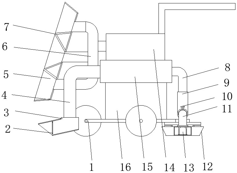
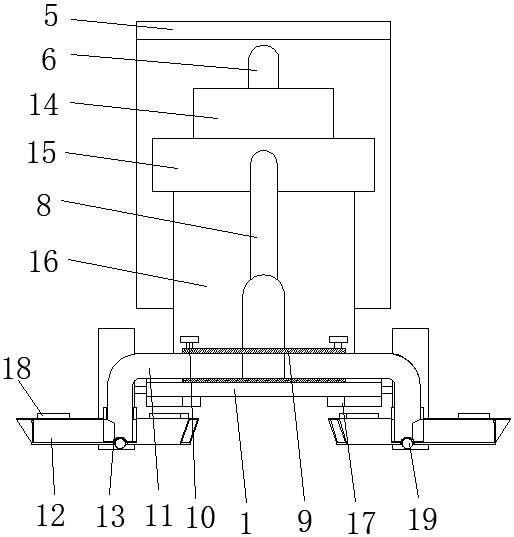
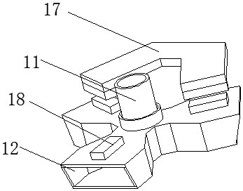
[0026] refer to Figure 1-4 , a thread collection device for textile production, comprising a frame 1, a vacuum cleaner 16 is fixedly installed on the top of the frame 1, and an exhaust hood 15 is fixedly installed on the top of the vacuum cleaner 16, and L-shaped The first suction pipe 4 and the second suction pipe 8 of the structure, the bottom end of the first suction pipe 4 is fixedly installed with the main collection tank 3 which is arranged obliquely, and the bottom of the second suction pipe 8 is fixedly installed with a three-way joint 9 , and both ends of the three-way joint 9 are plugged with extension pipes 11, the top of the three-way joint 9 is screwed with fastening bolts 10, the extension pipe 11 has an L-shaped structure, and the outside of the bottom end of the extension pipe 11 is sealed The bearing is equipped with a sub-collection tank 12, and the side of the vertical section of the extension pipe 11 is provided with a suction tank 13, and the suction tank...

Embodiment 2

[0034] refer to Figure 1-5 , a thread collection device for textile production. Compared with Example 1, the interior of the dust box 5 is fixedly equipped with a plurality of triangular-shaped dividing plates 7, and the side of the third suction pipe 6 is provided with A plurality of suction branch pipes interlaced with the partition plates 7, in the device rely on a plurality of partition plates 7 to isolate multiple independent areas inside the dust collection box 5, thereby increasing the suction force within the dust collection box 5 range, improving Dust collecting box 5 is to the collection efficiency of floating dust and lint.

[0035] When this embodiment is in use, the device relies on a plurality of partition plates 7 to isolate a plurality of independent areas inside the dust box 5, and generates suction in each independent area through the suction branch pipe, thereby increasing the dust within the scope of the dust box 5. The suction strength is improved, and the...


PUM


Abstract

The invention discloses a thread residue collecting device for textile production, and relates to the technical field of textile production. In order to solve the problem that impurities such as thread residues and broken cloth pieces are gathered at the bottom of a workbench or a manufacturing machine after a long time, and consequently cleaning is difficult, the thread residue collecting devicespecifically comprises a rack, a dust collector body is fixedly installed at the top of the rack, a draught hood is fixedly installed at the top of the dust collector body, a first suction pipe and asecond suction pipe which are of L-shaped structures are fixedly installed at the two ends of the draught hood correspondingly, and an obliquely-arranged main collecting tank is fixedly installed at the bottom end of the first suction pipe. According to the thread residue collecting device, in the advancing process of the device, the main collecting tank at the front end passes through the impurities such as the thread residues, the cloth scraps and garbage on the ground, one of auxiliary collecting tanks on the two sides extends to the bottom of the machine or the workbench, the impurities such as the thread residues, the cloth scraps and the garbage hidden on the two sides of a passageway are sucked out, and a good cleaning effect is achieved.

Description

technical field [0001] The invention relates to the technical field of textile production, in particular to a thread collecting device for textile production. Background technique [0002] Textile is a product made of textile fibers through processing and weaving. It is divided into two categories: woven fabric and knitted fabric. China is one of the earliest countries in the world to produce textiles. It is a big country in textile production and export. China's textile industry itself After years of development, the competitive advantage is very obvious. It has the most complete industrial chain in the world, the highest level of processing facilities, and the self-regulation ability of many developed industrial clusters to deal with market risks has been continuously enhanced, which provides the industry with a stable pace of development. Solid guarantee. [0003] In the process of textile production, many impurities such as thread ends and rags will be produced. These i...

Claims


Application Information

Patent Timeline
IPC IPC(8): B08B5/04B08B13/00
CPCB08B5/04B08B13/00
Inventor 李林王志平
Owner 江西省蒙恩纺织有限公司
Why Eureka
Try Eureka