A skin feeding device for bath tub processing

A skin and bathtub technology, which is applied in the field of skin feeding device for bath tub processing, can solve the problems of manual skin placement, cumbersome operation process, and labor-consuming, and achieve the effects of saving manpower, ensuring safety, and simple operation

Active Publication Date: 2022-06-24
临沂临港国有资产运营集团有限公司
8 Cites 0 Cited by

AI-Extracted Technical Summary

Problems solved by technology

[0006] In order to overcome the disadvantages of the cumbersome and manpower-intensive operation of the above-mentioned method, the present invention needs to manually place the epidermis during the operation, which easily burns the hands of workers and...

Abstract

The invention relates to a feeding device, in particular to a skin feeding device for bath tub processing. The technical problem to be solved by the present invention is how to design a skin feeding device for bath tub processing that is easy to operate, can save manpower, and can ensure the safety of operators during operation. The invention provides such a surface material feeding device for bathtub processing, comprising: a mounting seat, a heating box is installed on one side of the top; The cylinder is installed on the side of the top of the mounting seat close to the slide plate, and the telescopic rod of the first cylinder is connected with the slide plate; the moving assembly is arranged on the slide plate; the cover clip assembly is arranged on the heating box. In the present invention, the skin is added through the cooperation of the moving component and the cover clip component, so as to achieve the effect of adding the skin.

Application Domain

Domestic articles

Technology Topic

PhysicsBathtub +2

Image

  • A skin feeding device for bath tub processing
  • A skin feeding device for bath tub processing
  • A skin feeding device for bath tub processing

Examples

  • Experimental program(1)

Example Embodiment

[0023] The present invention will be further described below with reference to the accompanying drawings and embodiments.
[0024] first embodiment
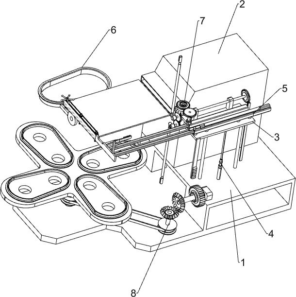
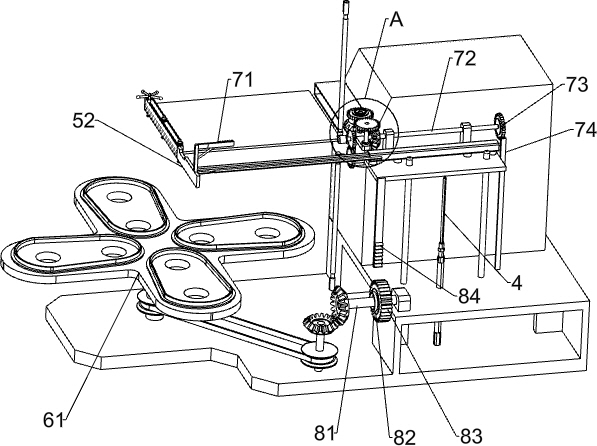
[0025] A skin feeding device for bath tub processing, such as Figure 1-3 As shown, it includes a mounting seat 1, a heating box 2, a sliding plate 3 and a first cylinder 4, a heating box 2 is installed on the right side of the top of the mounting seat 1, and a sliding plate 3 is slidably connected to the top of the mounting seat 1 on the front side of the heating box 2. A first air cylinder 4 is installed on the top of the mounting base 1 under the sliding plate 3. The telescopic rod of the first air cylinder 4 is connected with the sliding plate 3, and also includes a moving assembly 5 and a cover clip assembly 6. The sliding plate 3 is provided with a moving assembly 5, a heating box. 2 is provided with a cover clip assembly 6 .
[0026] The moving assembly 5 includes a second cylinder 51 , a sliding plate 52 , a first transmission gear 53 , a swing clamp 54 , a roller 55 , a magnet 56 , an internally threaded pipe 57 , a screw 58 , a sliding block 59 and an elastic member 591 , the sliding plate 3 A second air cylinder 51 is installed on the right side of the top, a sliding plate 52 is slidably connected to the sliding plate 3, the telescopic rod of the second air cylinder 51 is connected to the sliding plate 52, and the upper and lower sides of the left side of the sliding plate 3 are rotatably connected with a first transmission Gear 53, two first transmission gears 53 mesh with each other, a swing clamp rod 54 is connected to the transmission shaft of the first transmission gear 53, a roller 55 is rotatably connected to the swing clamp rod 54, and a magnet is connected to the end of the swing clamp rod 54 56, the upper part of the rear side of the sliding plate 52 is connected with three internal threaded pipes 57 in an evenly spaced and rotating manner. The three internal threaded pipes 57 are connected to each other through a belt and a pulley. The bottoms are connected to each other, and the lower part of the rear side of the sliding plate 52 is slidably connected with three sliding blocks 59 at even intervals.
[0027] The cover clip assembly 6 includes a placing plate 61, a fixing block 62, a pressing frame 64 and a sliding rod 65. A placing plate 61 is rotatably connected to the left side of the top of the mounting seat 1, and a fixing block 62 is connected to the rear side of the heating box 2. The fixing block 62 A clamping hole 63 is opened on the left side, a pressing frame 64 is rotatably connected to the left side of the fixing block 62 , and a sliding rod 65 is slidably connected to the pressing frame 64 , and the sliding rod 65 is matched with the clamping hole 63 .
[0028] When it is necessary to add skin to the bathtub skin, this device can be used. Initially, the first cylinder 4 and the second cylinder 51 are both in an extended state. First, the user can place the unheated skin on the screw 58 and slide it. Between the blocks 59, after the placement is completed, twist one of the internally threaded pipes 57 to rotate, one of the internally threaded pipes 57 rotates to drive all the internally threaded pipes 57 to rotate, and the rotation of the internally threaded pipes 57 drives the screw 58 to move downward. When the screw 58 is pressed When holding the bathtub skin, you can stop twisting the inner threaded pipe 57, then place the bathtub on the placing plate 61, then start the second cylinder 51 to retract the telescopic rod, and the retraction of the second cylinder 51 telescopic rod drives the sliding plate 52 moves to the right, and the sliding plate 52 moves to the right to drive all the devices on it to move to the right together, thereby driving the unheated skin to move to the heating box 2 for heating, thereby softening the skin. After the skin is softened, it can be Activate the second air cylinder 51 to extend the telescopic rod to drive the skin to move to the left so that the heating box 2 is moved out. After the skin is moved out of the heating box 2, one of the swing clamp bars 54 can be pulled to swing ninety degrees, and one of the swing clamp bars When the 54 swings, the first transmission gear 53 drives the other swing clamp rod 54 to swing together. When the two swing clamp rods 54 are swung, the magnets 56 on the two swing clamp rods 54 also attract each other. Continue to move to flatten it by the roller 55. When the skin is completely removed, the first cylinder 4 can be activated to retract the telescopic rod to drive the slide plate 3 to move downward, and the slide plate 3 moves downward to drive all the devices on it to move downward move, so as to drive the softened skin to move downward. When the skin moves to the bathtub, twist the pressing frame 64 to rotate 180 degrees, so that the pressing frame 64 is pressed above the skin, and then pull the sliding rod 65. Move to the right and snap it into the card hole 63 to fix the pressing frame 64. At this time, the suction device can be operated to make the skin stick to the bathtub. In this way, the skin can be loaded. After the skin is pasted, the first air cylinder can be started. 4. The extension of the telescopic rod can drive the sliding plate 3 to move upward.
[0029] Second Embodiment
[0030] On the basis of the first embodiment, as Figure 4-5As shown, it also includes a clamping assembly 7, and the clamping assembly 7 includes a driving rack 71, a first rotating shaft 72, a one-way gear 73, a transmission rack 74, a second rotating shaft 75, a first one-way clutch 76, a first one-way clutch 76, a The second transmission gear 77, the third transmission gear 78 and the bevel gear 79, the top left front side of the sliding plate 52 is connected with a driving rack 71, the top of the sliding plate 3 is rotatably connected with a first rotating shaft 72, and the right end of the first rotating shaft 72 is connected with a one-way gear 73. A transmission rack 74 is connected to the right side of the top of the mounting base 1, and the transmission rack 74 will mesh with the one-way gear 73. A second shaft 75 is rotatably connected to the top of the left side of the slide plate 3, and the left end of the first shaft 72 is connected to the upper A transmission shaft of a transmission gear 53 is connected, a first one-way clutch 76 is connected to the second shaft 75, a second transmission gear 77 is connected to the first one-way clutch 76, and the top of the sliding plate 3 on the front side of the second shaft 75 is rotated. A third transmission gear 78 is connected, the third transmission gear 78 meshes with the second transmission gear 77, the left side of the first rotating shaft 72 and the middle of the second rotating shaft 75 are connected with a bevel gear 79, the two bevel gears 79 mesh with each other, the third The transmission gear 78 is meshed with the drive rack 71 .
[0031] When the sliding plate 52 moves left and right, it also drives the driving rack 71 to move left and right together. When the driving rack 71 moves to the right to mesh with the third transmission gear 78, the driving rack 71 continues to move to drive the third transmission gear 78 to rotate. At this time, the second rotating shaft 75 will not rotate under the action of the first one-way clutch 76. When the driving rack 71 moves to the left to engage with the third transmission gear 78, the driving rack 71 continues to move to drive the third transmission. The rotation of the gear 78, the rotation of the third transmission gear 78 drives the rotation of the second transmission gear 77, the rotation of the second transmission gear 77 drives the rotation of the second rotation shaft 75, the rotation of the second rotation shaft 75 drives the rotation of the first rotation shaft 72 through the bevel gear 79, the rotation of the first rotation shaft The rotation of 72 drives the first transmission gear 53 to rotate, and the rotation of the first transmission gear 53 drives the swing clamp rod 54 to rotate. When the driving rack 71 moves to disengage from the third transmission gear 78, the swing clamp rod 54 rotates just ninety degrees. In this way, there is no need to manually pull the swing clamp rod 54 to rotate, and the slide plate 3 also drives the one-way gear 73 to move up and down through the first rotating shaft 72 when moving up and down. Since the one-way gear 73 is set in one direction, it will not drive the first rotating shaft 72 to rotate. After the one-way gear 73 moves upward to mesh with the transmission rack 74, the one-way gear 73 continues to move through the transmission rack 74 to rotate, and the one-way gear 73 rotates. The rotation of 73 drives the swinging clamp rod 54 to rotate and reset through the first rotating shaft 72, so that there is no need to manually rotate the swinging clamp rod 54 to rotate, which effectively saves manpower.
[0032] like Figure 4 As shown, it also includes a rotating assembly 8, the rotating assembly 8 includes a third rotating shaft 81, a second one-way clutch 82, a cylindrical gear 83 and a spur gear 84, and a third rotating shaft 81 is rotatably connected to the right side of the top of the mounting seat 1 , a second one-way clutch 82 is connected to the third shaft 81, a spur gear 83 is connected to the second one-way clutch 82, a spur gear 84 is connected to the left front side of the bottom of the slide plate 3, and the spur gear 84 will mesh with the spur gear 83 , the third rotating shaft 81 is connected with the placing plate 61 through a belt drive and a bevel gear drive.
[0033] When placing the bathtub, the bathtub can be placed on the placing plate 61 at even intervals along the circumferential direction. When the slide plate 3 moves up and down, it also drives the straight rack 84 to move downward. When the straight rack 84 moves downward, the second one-way The third rotating shaft 81 will not rotate under the action of the clutch 82. After the spur gear 84 moves upward to mesh with the spur gear 83, the spur gear 84 continues to move upward to drive the third rotating shaft 81 to rotate through the spur gear 83. The third rotating shaft The rotation of 81 drives the rotation of the placing plate 61, so as to replace the bathtub that needs to be added with skin, so that there is no need to manually add and remove the bathtub frequently.
[0034] The above-mentioned embodiments only represent the preferred embodiments of the present invention, and the descriptions thereof are specific and detailed, but should not be construed as limiting the scope of the present invention. It should be pointed out that for those of ordinary skill in the art, without departing from the concept of the present invention, several modifications, improvements and substitutions can be made, which all belong to the protection scope of the present invention. Therefore, the protection scope of the patent of the present invention should be subject to the appended claims.

PUM

no PUM

Description & Claims & Application Information

We can also present the details of the Description, Claims and Application information to help users get a comprehensive understanding of the technical details of the patent, such as background art, summary of invention, brief description of drawings, description of embodiments, and other original content. On the other hand, users can also determine the specific scope of protection of the technology through the list of claims; as well as understand the changes in the life cycle of the technology with the presentation of the patent timeline. Login to view more.

Similar technology patents

Aluminum pipe bagging device

Owner:昆山市工业技术研究院有限责任公司

Method and device for testing webpage downloading speed of mobile terminal device

ActiveCN103581987Asave human effortIncrease sampling points
Owner:TENCENT TECH (SHENZHEN) CO LTD

Material pulverizing and sieving device

Owner:CHENZHOU JINTONG INFORMATION TECH CO LTD

Carrying trolley for large-size oil cylinder

Owner:ANQING TIANRUN ENG MACHINERY

Classification and recommendation of technical efficacy words

  • easy to operate
  • save human effort

Lancet device

InactiveUS7303573B2inexpensively mass-producedeasy to operate
Owner:ABBOTT DIABETES CARE INC

Rapid and non-invasive optical detection of internal bleeding

InactiveUS20050065436A1easy to operaterapid and accurate result
Owner:HO WINSTON ZONH +2

Self-supporting car washing method and car washer

ActiveCN105957268Asave human effortsave water
Owner:盐城东方兴达农业发展有限公司

Drilled hole effective extraction radius measuring method based on gas content method

InactiveCN104121011AEliminate outstanding hazardssave human effort
Owner:CHINA COAL TECH ENG GRP CHONGQING RES INST

Vehicle-mounted visual sensing system with matched multi-cameras

InactiveCN106926800Asave human effortReduce time cost and economic cost
Owner:CHONGQING UNIV +1
Why Eureka
Try Eureka