Check patentability & draft patents in minutes with Patsnap Eureka AI!

Power transmission tower capable of utilizing thin-wall buckling torsion and preventing extension arm torsion

A transmission tower and anti-extension technology, which is applied in the field of transmission towers, can solve the problems of adverse effects on the safety of the main tower, poor stability of the rotating structure, and low safety, so as to improve stability and safety, increase weight, and improve safety Effect

Active Publication Date: 2020-11-03
马鞍山辰慕芸智能科技发展有限公司
View PDF10 Cites 0 Cited by
  • Summary
  • Abstract
  • Description
  • Claims
  • Application Information

AI Technical Summary

Problems solved by technology

Especially in the case of anti-symmetric disconnection accident conditions, the torque on both sides will be superimposed, and under the action of this torque, it will have a very adverse effect on the safety of the main tower; it is necessary to reduce the torque effect through a rotatable structure, but in the transmission tower Under normal use, the stability of the rotating structure is poor, and the outer extension end of the low hanging point single rotating arm has a heavier specific gravity than the connection end of the main tower, which further leads to poor stability and low safety of the transmission tower under normal use, so there is an urgent need for a The structure is stable in normal use, and the low-hanging-point single-swivel arm rotates relative to the main tower in case of an accident

Method used


Image

  • Power transmission tower capable of utilizing thin-wall buckling torsion and preventing extension arm torsion
  • Power transmission tower capable of utilizing thin-wall buckling torsion and preventing extension arm torsion
  • Power transmission tower capable of utilizing thin-wall buckling torsion and preventing extension arm torsion

Examples


Embodiment Construction

[0022] The following will clearly and completely describe the technical solutions in the embodiments of the present invention with reference to the accompanying drawings in the embodiments of the present invention. Obviously, the described embodiments are only some, not all, embodiments of the present invention. Based on the embodiments of the present invention, all other embodiments obtained by persons of ordinary skill in the art without making creative efforts belong to the protection scope of the present invention.

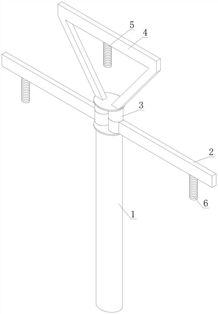
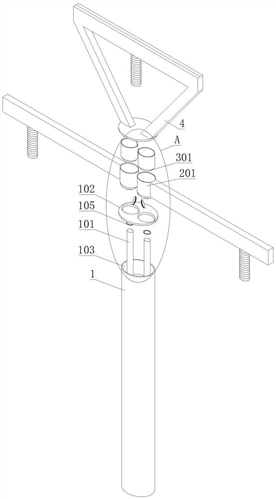
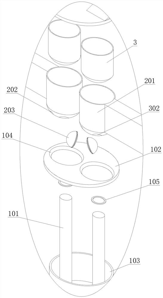
[0023] refer to figure 1 , a transmission tower using thin-wall buckling torsion anti-outrigger torsion, including a main tower 1, a low hanging point single rotating arm 2, a thin-walled tube 3 and a high hanging point bracket 4, the main tower 1 and a high hanging point bracket 4 A low-hanging-point single-swivel arm 2 is installed between them, and a thin-walled pipe 3 is arranged between the low-hanging-point single-swinging arm 2 and the high-hanging poin...


PUM


Abstract

The invention discloses a power transmission tower capable of utilizing thin-wall buckling torsion and preventing extension arm torsion, and belongs to the technical field of power transmission towers. The power transmission tower comprises a main tower, a low-hanging-point single rotating arm, a thin-wall pipe and a high-hanging-point bracket, the low-hanging-point single rotating arm is arrangedbetween the main tower and the high-hanging-point bracket, and the thin-wall pipe is arranged between the low-hanging-point single rotating arm and the high-hanging-point bracket; and the main towercomprises main tower rotating shafts, a main tower clamping plate, a main tower sand groove and a shaft hole, the main tower sand groove with an opening in the upper end is formed in the top end of the main tower, the two main tower rotating shafts are welded to the lower bottom surface of the main tower sand groove, and the main tower clamping plate is welded to the end opening in the upper end of the main tower sand groove. The stability and safety of ordinary use are improved, the low-hanging-point single rotating arm rotates in case of an accident, the arm of force of horizontal force after rotation is reduced, the bending moment of the low-hanging-point single rotating arm is reduced, and the torque transmitted to the main tower is also reduced, so that the safety of the main tower isalso improved, and the corresponding manufacturing cost can also be reduced.

Description

technical field [0001] The invention relates to the technical field of power transmission towers, in particular to a power transmission tower using thin-wall buckling torsion anti-outrigger torsion. Background technique [0002] The transmission tower is a common high-rise structure, which is usually subjected to gravity load, wind load, earthquake load, etc. At the same time, various loads on the transmission line on the transmission tower are finally transmitted to the transmission tower. Under normal circumstances, The force generated by the transmission line on the transmission tower on the transmission tower is close to balance, so the transmission tower is only affected by the vertical force and a small part of the unbalanced force. However, when the accident occurs, the transmission line on the transmission tower After an asymmetrical break, the transmission line will not only generate vertical loads but also horizontal loads on the transmission tower. Especially in ...

Claims


Application Information

Patent Timeline
IPC IPC(8): E04H12/02E04H12/18
CPCE04H12/02E04H12/18
Inventor 张辰啸王邺夏蔓芸刘阳杨帆王家发孙成翔胡友天周佳慧陈富长唐丽园贺成英健俞斯琦
Owner 马鞍山辰慕芸智能科技发展有限公司
Features
  • R&D
  • Intellectual Property
  • Life Sciences
  • Materials
  • Tech Scout
  • Unparalleled Data Quality
  • Higher Quality Content
  • 60% Fewer Hallucinations
Learn More