Compressor and refrigeration equipment
A compressor and casing technology, applied in the field of compressors, can solve problems such as low work efficiency and affect compressor production efficiency, and achieve the effects of facilitating assembly operations, realizing product serialization design, and reducing costs.
- Summary
- Abstract
- Description
- Claims
- Application Information
AI Technical Summary
Problems solved by technology
Method used
Image

Examples
Embodiment 1
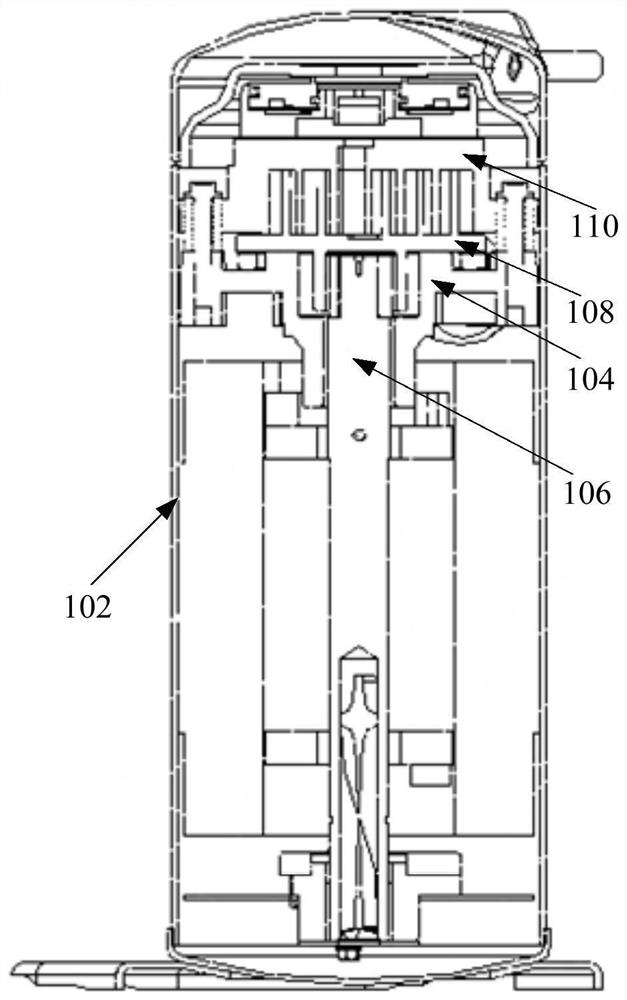
[0048] Such as figure 1 and figure 2 As shown, the first embodiment of the present invention proposes a compressor, including: a casing 102 and a main frame 104 ; the main frame 104 includes a guide structure 1042 .
[0049] Among them, such as figure 1 As shown, the main frame 104 is disposed inside the casing 102 and can be connected to the inner wall of the casing 102 by welding or other connection methods. The guide structure 1042 can be used in cooperation with the tooling to complete the positioning and installation of the main frame 104 .
[0050] Specifically, the compressor has extremely high requirements on the positioning accuracy of the main frame 104 . During the assembly process of the compressor proposed by the present invention, the tooling is inserted into the inside of the guide structure 1042 . The tooling itself is a retractable structure that can be driven by hydraulic pressure or other means. When the tooling penetrates into the guide structure 1042...
Embodiment 2
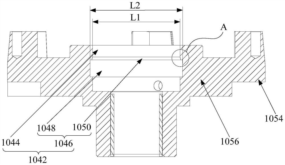
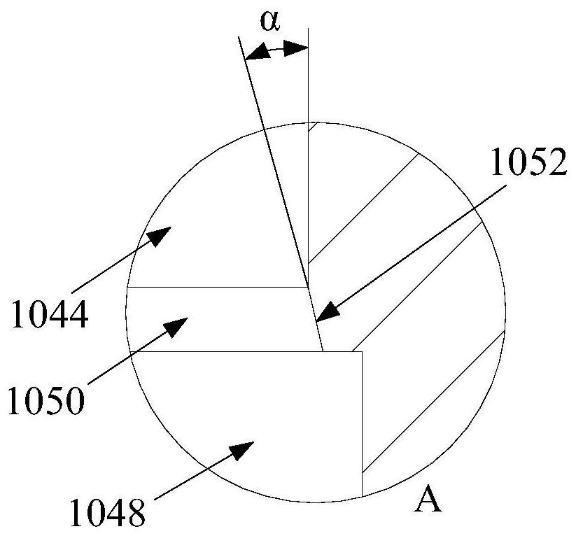
[0054] Such as figure 1 , figure 2 and image 3 As shown, the second embodiment of the present invention proposes a compressor, including: a casing 102 and a main frame 104; the main frame 104 includes a body 1056 and a guide structure 1042; the guide structure 1042 includes a guide cavity 1044 and a centering cavity 1046 .
[0055] Among them, such as figure 1 As shown, the main frame 104 is disposed inside the casing 102 and can be connected to the inner wall of the casing 102 by welding or other connection methods. The guide structure 1042 can be used in cooperation with the tooling to complete the positioning and installation of the main frame 104 .
[0056] Specifically, such as figure 2 As shown, the guide cavity 1044 is arranged on the upper surface of the body 1056 , and one end of the guide cavity 1044 is open; In the process of assembling the compressor, the tooling is first in a contracted state, and the tooling in the contracted state enters the inside of t...
Embodiment 3
[0073] Such as figure 1 and figure 2As shown, the third embodiment of the present invention proposes a compressor, including: a casing 102, a main frame 104, a rotating shaft 106, a first scroll 108 and a second scroll 110; the main frame 104 includes a guide structure 1042.
[0074] Among them, such as figure 1 As shown, the main frame 104 is disposed inside the casing 102 and can be connected to the inner wall of the casing 102 by welding or other connection methods. The guide structure 1042 can be used in cooperation with the tooling to complete the positioning and installation of the main frame 104 . The beneficial effect of the guide structure 1042 is the same as that of the first and second embodiments, and will not be repeated here.
[0075] In addition, if figure 1 As shown, the rotating shaft 106 passes through the main frame 104 and is connected to the first scroll 108, the first scroll 108 is connected to the rotating shaft 106, and can perform a rotary motion...
PUM
 Abstract
Description
Claims
Application Information