Magnetizing head water-cooling circulation system

A circulatory system, magnetic head technology, applied in the direction of magnetic objects, transformer/inductor cooling, electrical components, etc., can solve the problems of low heat absorption efficiency, reduce the economic loss of the service life of the magnetic head, small contact surface, etc., and achieve extended use. The effect of lifespan, reducing work intensity and improving efficiency

Active Publication Date: 2020-11-03
宏辉磁电科技(安徽)有限公司
View PDF10 Cites 1 Cited by
  • Summary
  • Abstract
  • Description
  • Claims
  • Application Information

AI Technical Summary

Problems solved by technology

[0004] The purpose of the present invention is to provide a kind of magnetized magnetic head water-cooling circulation system, to solve the problem that the magnetized magnetic head on the market currently proposed by the above-mentioned background technology is a kind of new industry, itself has good development prospect, yet, the magnetized magnetic head is in use A large amount of heat will be generated at the time. The existing technology uses a square sleeve to absorb heat. Due to the small contact surface, the heat absorption efficiency is low, which greatly reduces the service life of the magnetized magnetic head and increases the extra economic loss in the production process of the enterprise. The problem

Method used


Image

  • Magnetizing head water-cooling circulation system
  • Magnetizing head water-cooling circulation system
  • Magnetizing head water-cooling circulation system

Examples


Embodiment Construction

[0020] The following will clearly and completely describe the technical solutions in the embodiments of the present invention with reference to the accompanying drawings in the embodiments of the present invention. Obviously, the described embodiments are only some, not all, embodiments of the present invention.

[0021] In describing the present invention, it should be understood that the terms "upper", "lower", "front", "rear", "left", "right", "top", "bottom", "inner", " The orientation or positional relationship indicated by "outside", etc. is based on the orientation or positional relationship shown in the drawings, and is only for the convenience of describing the present invention and simplifying the description, rather than indicating or implying that the referred device or element must have a specific orientation, so as to Specific orientation configurations and operations, therefore, are not to be construed as limitations on the invention.

[0022] refer to Figure ...


PUM


Abstract

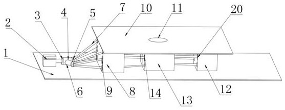
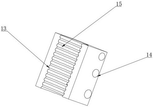
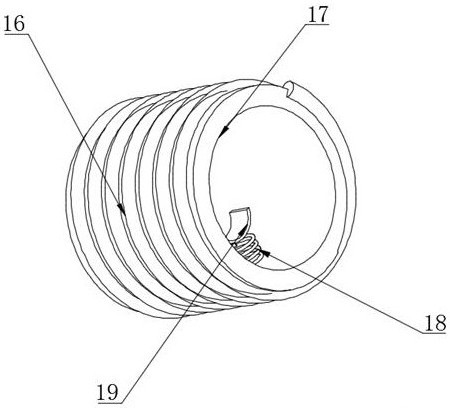
The invention discloses a magnetizing head water-cooling circulation system, and the system comprises a base, wherein a magnetizing round pipe is fixedly arranged on the upper side of the base, a coilis wound around the outer ring of the magnetizing round pipe, a fixed device is arranged on the inner side wall of the magnetizing round pipe, two symmetrical mounting blocks are fixedly connected tothe upper side wall of the base, and a spiral groove is formed in the concave part of the mounting block. The invention relates to the technical field of magnetizing magnetic heads, in particular toa magnetizing magnetic head water-cooling circulation system, which utilizes parts such as hoses, a first condensation block, a first condensation hole, a mounting block, a through hole, a second condensation block and the like to absorb heat generated by a coil; water in the three hoses passes through the mounting block to absorb the heat, and the heat absorbed by the water passing through the mounting block is absorbed by the first condensation block when flowing through the first condensation hole or absorbed by the second condensation block when flowing through the second condensation hole, so the heat dissipation efficiency is improved, the service life of the water-cooling circulation system is prolonged, and the service life of the magnetizing magnetic head is prolonged.

Description

technical field [0001] The invention relates to the technical field of magnetized magnetic heads, in particular to a water cooling circulation system for magnetized magnetic heads. Background technique [0002] Magnetization, to magnetize a magnetic substance or to increase the magnetism of a magnet with insufficient magnetism. Generally, the magnetic object to be magnetized is placed in the magnetic field formed by the coil passing through the direct current. [0003] In modern times, as a new type of industry, the magnetized magnetic head itself has good development prospects. However, the magnetized magnetic head will generate a lot of heat when it is used. The existing technology uses the water inside the square sleeve to absorb heat, making the square Insufficient contact between the inner surface of the sleeve and the turns leads to low heat absorption efficiency of the heat absorbing device, which increases the cooling efficiency of the magnetized magnetic head, grea...

Claims


Application Information

Patent Timeline
Patent Type & Authority Applications(China)
IPC IPC(8): H01F13/00H01F27/16
CPCH01F13/00H01F27/16
Inventor 陈锦华
Owner 宏辉磁电科技(安徽)有限公司
Why Eureka
Try Eureka