Control circuit for driving relay to be quickly switched on and off

A technology for controlling circuits and relays, applied in the direction of relays, circuits, electrical components, etc., can solve the problem of high power requirements

Pending Publication Date: 2020-11-03
CHONGQING CHUANYI AUTOMATION
View PDF0 Cites 0 Cited by
  • Summary
  • Abstract
  • Description
  • Claims
  • Application Information

AI Technical Summary

Problems solved by technology

When the relay is not working, the high driving voltage VH charges the energy storage capacitor C4 to ensure sufficient voltage to drive the contacts of the relay to pull in; after the relay pulls in, the high driving voltage VH stops driving the relay under the action of the current limiting resistor R8 , continue to supply power to the relay from the low driving voltage VL, thereby reducing the heat generation of the relay coil, but this method requires dual power supply, which has higher requirements for power supply

Method used


Image

  • Control circuit for driving relay to be quickly switched on and off
  • Control circuit for driving relay to be quickly switched on and off
  • Control circuit for driving relay to be quickly switched on and off

Examples


Embodiment Construction

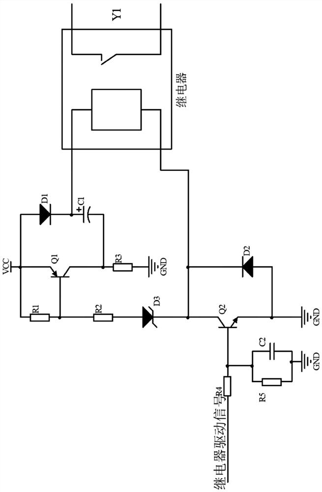
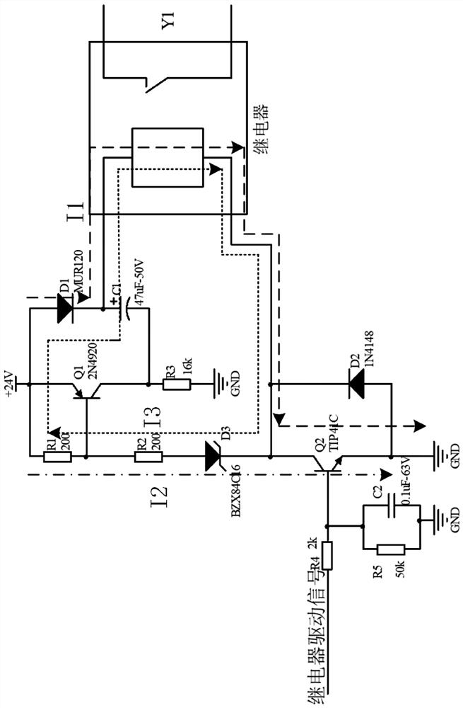
[0021] see Figure 1 to Figure 2 , a control circuit for driving a relay to turn on and off quickly, including a relay Y1, the first node of the coil of the relay Y1 is connected to a power supply through a boost circuit, and the second node of the coil of the relay Y1 receives a relay driving signal through a switch control circuit, that is, through The boost circuit and the switch control circuit jointly realize the opening and closing of the relay Y1. The boost circuit includes a PNP transistor Q1, an energy storage capacitor C1, a first diode D1, and a first resistor R1 and a second resistor R2 for voltage division. The emitter of the PNP transistor Q1, The anode of the first diode D1 is connected to the power supply, the base of the PNP transistor Q1 is connected to the power supply through the first resistor R1, the collector of the PNP transistor Q1, and the negative pole of the energy storage capacitor C1 are grounded through the third resistor R3. The third resistor ...


PUM


Abstract

A control circuit for driving a relay to be rapidly switched on and off comprises a relay, a first node of a coil of the relay is connected with a power supply through a boosted circuit, a second nodeof the coil of the relay receives a relay driving signal through a switch control circuit, and the boosted circuit comprises a PNP type triode, a first resistor, a second resistor, an energy storagecapacitor and a first diode. An emitter of the PNP type triode and the anode of the first diode are connected with a power supply, the base of the PNP type triode is connected with the power supply through the first resistor, the collector of the PNP type triode and the cathode of the energy storage capacitor are grounded through the third resistor, and the cathode of the first diode and the anodeof the energy storage capacitor are connected with the first node of the coil of the relay. The switch control circuit comprises an NPN type triode and a fourth resistor, the base electrode of the PNP type triode is connected with the collector electrode of the NPN type triode and the second node of the coil of the relay through the second resistor and a voltage stabilizing tube, the base electrode of the NPN type triode receives relay driving signals through the fourth resistor, and the emitting electrode of the NPN type triode is grounded.

Description

technical field [0001] The invention relates to the technical field of drive control of relays, in particular to a control circuit for driving relays to switch on and off quickly. Background technique [0002] Relays play an important role in our daily life and in all walks of life, such as plug-in card power-taking switches in life, touch doorbells, and drive of screen doors in rail transit, low-voltage and small-current control of high-voltage and large-scale power equipment. Current, frequency converter and pre-charge protection of active power filter circuit, etc. The relay is composed of a coil and a contact, and has two working states of on and off. When the relay is turned on, a higher voltage is required to provide sufficient energy for the contact to pull in during the process of contact pull-in, and the contact pull-in Only a lower voltage is required to keep the contacts in the closed state after closing. If in order to ensure the reliable opening of the relay, t...

Claims


Application Information

Patent Timeline
Patent Type & Authority Applications(China)
IPC IPC(8): H01H47/02H01H47/22
CPCH01H47/02H01H47/22
Inventor 房占凯徐光健杨自清陈果方浩马辉刘霜
Owner CHONGQING CHUANYI AUTOMATION
Why Eureka
Try Eureka