Waste liquid collection device for operating room nursing

A waste liquid collection and operating room technology, applied in the field of medical appliances, can solve problems such as easy spillage, waste liquid cannot be effectively separated, single function, etc., and achieve the effect of improving functionality and sufficient and efficient solid-liquid separation

Inactive Publication Date: 2020-11-06
日照市岚山区人民医院
View PDF1 Cites 5 Cited by
  • Summary
  • Abstract
  • Description
  • Claims
  • Application Information

AI Technical Summary

Problems solved by technology

[0004] However, the height of the above-mentioned device cannot be adjusted, and it is easy to spill when the medical staff dumps the waste liquid at hand, and the device cannot effectively separate the waste liquid left in the solid waste, such as medicine in a medicine bottle, etc. Relatively simple

Method used


Image

  • Waste liquid collection device for operating room nursing
  • Waste liquid collection device for operating room nursing
  • Waste liquid collection device for operating room nursing

Examples


Embodiment 1

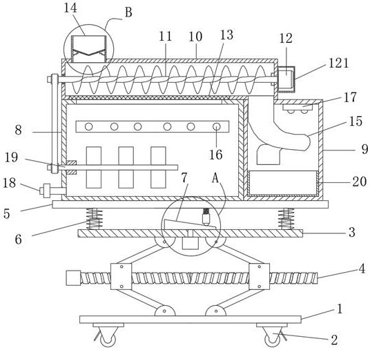
[0032] The invention provides a technical solution: a waste liquid collection device for nursing care in an operating room, including a base plate 1, rollers 2 are arranged at the four corners of the bottom end of the base plate 1, a lifting plate 3 is arranged above the base plate 1, and the lifting plate 3 and the base plate 1 is connected with a lifting mechanism 4, a mounting plate 5 is arranged above the lifting plate 3, and a spring telescopic rod 6 is arranged between the four corners of the bottom surface of the mounting plate 5 and the top surface of the lifting plate 3, and between the middle part of the lifting plate 3 and the middle part of the mounting plate 5 An up and down shaking mechanism 7 is provided, a waste liquid tank 8 is provided on the left side of the top of the mounting plate 5, a waste residue tank 9 is arranged on the right side of the waste liquid tank 8, and a cylinder 10 is provided on the top of the waste liquid tank 8, and the top of the cylinde...

Embodiment 2

[0038] Compared with Embodiment 1, there are the following differences. The lower part of the left side wall of the waste liquid tank 8 is rotatably provided with a stirring mechanism 19. The stirring mechanism 19 includes a rotating shaft 191, and stirring blades 193 are uniformly arranged on the rod wall at the right part of the rotating shaft 191. The left end of the rotating shaft 191 runs through the left end of the waste liquid tank 8 and is connected with a transmission belt 192, and the upper part of the transmission belt 192 is connected with the left end of the conveying screw 11;

[0039] During specific implementation, after the medicament is added in the waste liquid tank 8, the stirring mechanism 19 can accelerate its mixing reaction efficiency, and the stirring mechanism 19 and the conveying screw 11 share a set of motors, which can reduce power consumption.

Embodiment 3

[0041] Compared with Embodiment 1, there are the following differences. The left and right sides of the inner cavity of the waste inlet nozzle 14 are correspondingly hinged with baffles 141, and a second spring 142 is connected between the bottom surface of the baffle 141 and the side wall of the adjacent waste inlet nozzle 14; When the solid waste is poured in, the buffering effect is activated, and it can also prevent the smell from overflowing to a certain extent.

[0042] In the solution, a protective cover 121 is provided around the driving motor 12 for protecting the motor.

[0043] In the scheme, the bottom of the waste slag discharge pipe (15) is a spiral pipe, which can reduce the risk of broken bottles of solid waste.


PUM


Abstract

The invention discloses a waste liquid collection device for operating room nursing in the technical field of medical instruments. The waste liquid collection device comprises a bottom plate; rollersare arranged on four corners of the bottom end of the bottom plate; a lifting plate is arranged above the bottom plate; a lifting mechanism is connected between the lifting plate and the bottom plate;a mounting plate is arranged above the lifting plate; and spring telescopic rods are arranged between four corners of the bottom surface of the mounting plate and the top surface of the lifting plate. According to the invention, by structural designs of a conveying helix, a barrel, filtering mesh openings and the like, solid waste and liquid waste can be effectively separated in the rolling process so as to facilitate the subsequent waste treatment process; by structural designs of an up-and-down shaking mechanism, the spring telescopic rods and the like, solid-liquid separation is more sufficient and efficient; by a design of the lifting mechanism, a height of the collection device can be regulated so as to adapt to medical personnel with different heights for use; and according to the invention, waste liquid and waste residues can also be subjected to disinfection and sterilization treatment to a certain degree, so that functionality of the collection device is improved.

Description

technical field [0001] The invention relates to the technical field of medical appliances, in particular to a waste liquid collection device for nursing in an operating room. Background technique [0002] The operating room usually needs nursing at the same time during the operation, and the nursing work will generate a lot of medical waste. When collecting garbage, the way of putting garbage bags in garbage bins is usually used. Medical waste is often accompanied by some waste liquid. The liquid will even flow out from the garbage bag, polluting the external environment, and it is very difficult to handle. And the garbage bag is simply set on the garbage can, when placing waste in the garbage can, because the garbage bag lacks necessary fixing, the upper end of the garbage bag will come off from the garbage can, and the garbage will be thrown into the garbage can and the garbage bag. In between, it is very inconvenient to deal with. [0003] Patent CN201820580384.2 discl...

Claims


Application Information

Patent Timeline
Patent Type & Authority Applications(China)
IPC IPC(8): A61G12/00A61L2/08A61L2/16A61L11/00B01D29/03B01J19/18
CPCA61G12/00A61L2/08A61L2/16A61L11/00B01D29/03B01J19/18
Inventor 李志艳胡淑丽刘秋芬
Owner 日照市岚山区人民医院
Why Eureka
Try Eureka