Automatic iron sheet indenting machine
An indentation machine and automatic technology, applied in metal processing equipment, forming tools, manufacturing tools, etc., can solve the problems of low indentation efficiency of iron sheets, difficult to control indentation quality, etc., to shorten the preparation time, improve the indentation effect, Improve the effect of shaping
- Summary
- Abstract
- Description
- Claims
- Application Information
AI Technical Summary
Problems solved by technology
Method used
Image
Examples
specific Embodiment approach 1
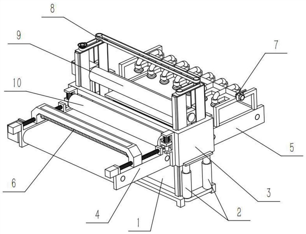
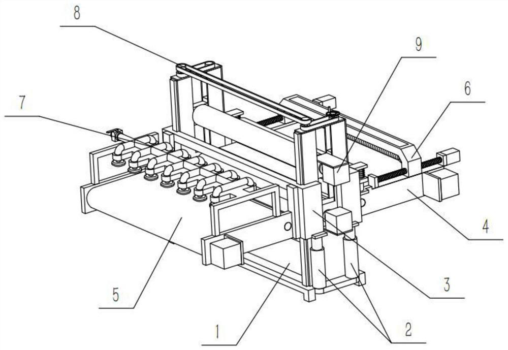
[0035] Combine below Figure 1-13Describe this embodiment, an automatic indentation machine for iron sheet, including hydraulic support rods 2 and lift frames 3, four hydraulic support rods 2 are provided, and two hydraulic pressure rods are fixedly connected to the lower sides of the two ends of the lift frame 3 Support rod 2, the iron sheet automatic creasing machine also includes a support seat 1, a feeding mechanism 4, a discharging mechanism 5, a heating mechanism 6, a cooling mechanism 7, an adjusting mechanism 8, an upper creasing mechanism 9 and a pressing mechanism 10, The two ends of the support base 1 are respectively fixedly connected with two hydraulic support rods 2, and the lift frame 3 is slidably connected to the support base 1, and the feeding mechanism 4 and the discharge mechanism 5 are fixedly connected to the ends of the lift frame 3 respectively. At the front and rear ends, the heating mechanism 6 is slidably connected to the upper end of the feeding mec...
specific Embodiment approach 2
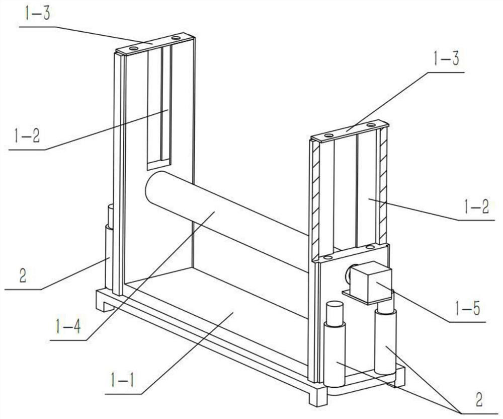
[0037] Combine below Figure 1-13 Describe this embodiment, this embodiment will further explain the first embodiment, the support base 1 includes a support frame 1-1, a sliding groove 1-2, an end plate 1-3, a lower indentation tube 1-4 and a motor I1- 5. Both sides of the upper end of the support frame 1-1 are provided with sliding grooves 1-2, and two end plates 1-3 are provided, and the two end plates 1-3 are respectively fixedly connected to the two sliding grooves 1 -2, the lower indentation tube 1-4 is rotatably connected to the middle part of the support frame 1-1, the output shaft of the motor I1-5 is fixedly connected to the lower indentation tube 1-4, and the motor I1-5 Fixedly connected to the support frame 1-1, two hydraulic support rods 2 are fixedly connected to the upper sides of the two ends of the support frame 1-1, and the lifting frame 3 is slidably connected to the support frame 1-1. The two ends of the indentation mechanism 9 are slidably connected in the...
specific Embodiment approach 3
[0040] Combine below Figure 1-13 Describe this embodiment, this embodiment will further explain the first embodiment, the feeding mechanism 4 includes a feeding frame 4-1, a pulley I4-2, a feeding belt 4-3, a sliding frame 4-4, and a motor II4 -5, threaded rod I4-6 and motor III4-7, two pulleys I4-2 are provided, and the two pulleys I4-2 are connected to the front and rear ends of the feed frame 4-1 in rotation respectively, and the two The first pulley 4-2 is connected through the transmission of the feeding belt 4-3, and the sliding frame 4-4 is provided with two, and the two sliding frames 4-4 are respectively fixedly connected to the left and right sides of the rear end of the feeding frame 4-1. , the motor II4-5 is fixedly connected to the front end of the feed frame 4-1, and the output shaft of the motor II4-5 is fixedly connected to the front pulley I4-2, and the threaded rod I4-6 is provided with two, The two threaded rods Ⅰ4-6 are respectively rotatably connected to...
PUM
 Abstract
Description
Claims
Application Information
 - R&D
- Intellectual Property
- Life Sciences
- Materials
- Tech Scout
- Unparalleled Data Quality
- Higher Quality Content
- 60% Fewer Hallucinations
Browse by: Latest US Patents, China's latest patents, Technical Efficacy Thesaurus, Application Domain, Technology Topic, Popular Technical Reports.
© 2025 PatSnap. All rights reserved.Legal|Privacy policy|Modern Slavery Act Transparency Statement|Sitemap|About US| Contact US: help@patsnap.com


