Metal rod shearing device with grinding function

A shearing device, metal rod technology, applied in the direction of manufacturing tools, other manufacturing equipment/tools, etc., can solve the problems of insufficient shearing accuracy, waste of manpower, bending of metal rods, etc., to achieve the effect of mass production and energy saving

Inactive Publication Date: 2020-11-06
深圳市壹闻科技有限公司
View PDF0 Cites 0 Cited by
  • Summary
  • Abstract
  • Description
  • Claims
  • Application Information

AI Technical Summary

Problems solved by technology

[0003] Existing steel bar shearing devices generally use manpower to cut steel bar shears. This kind of cutting method wastes manpower, is not efficient, and the cutting accuracy is not enough, which is likely to cause inconsistent lengths and is not suitable for mass production. , and the metal rod may be bent when it is squeezed, which will affect the cutting accuracy

Method used


Image

  • Metal rod shearing device with grinding function
  • Metal rod shearing device with grinding function
  • Metal rod shearing device with grinding function

Examples


Embodiment Construction

[0028] The present invention is described in further detail now in conjunction with accompanying drawing. These drawings are all simplified schematic diagrams, which only illustrate the basic structure of the present invention in a schematic manner, so they only show the configurations related to the present invention.

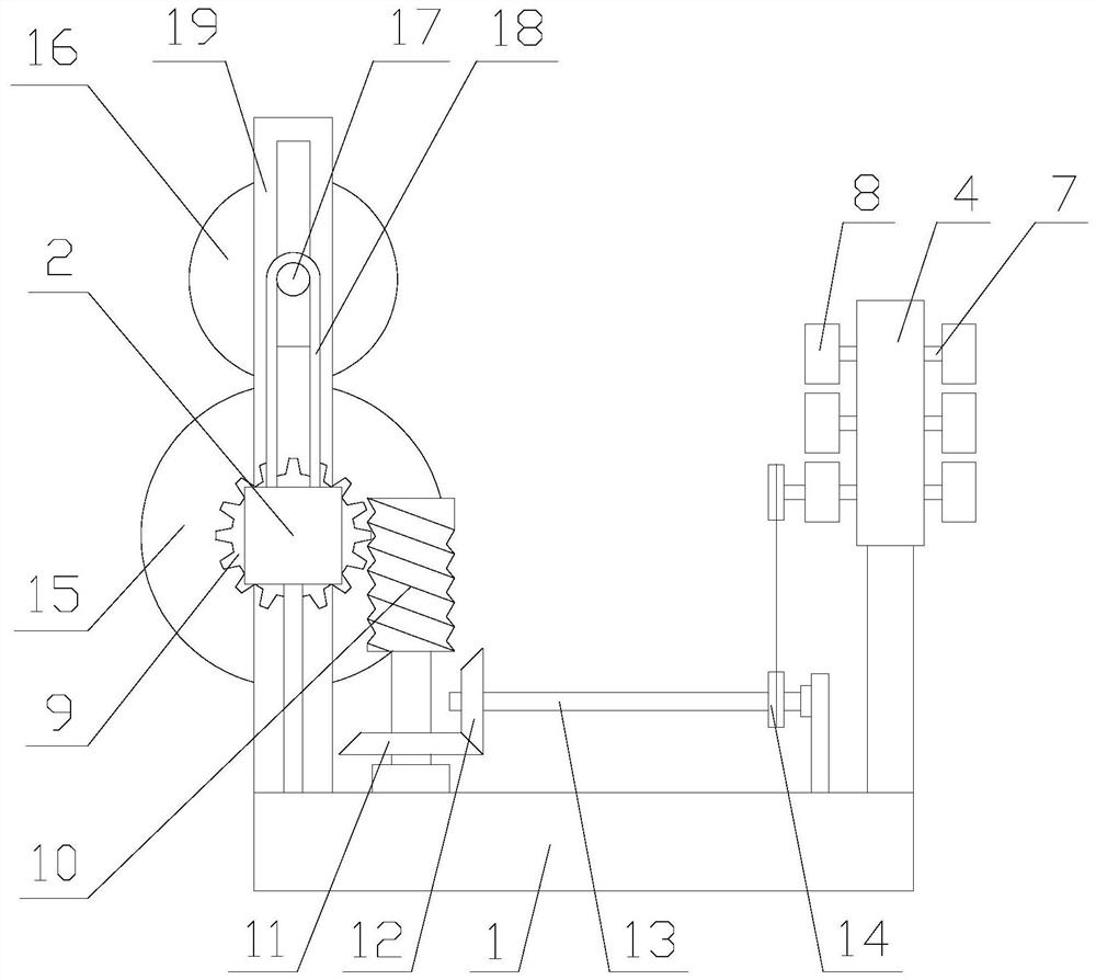
[0029] Such as figure 1 As shown, a metal rod shearing device with a grinding function includes a base 1, a driving mechanism, a grinding mechanism and a shearing mechanism. The driving mechanism is arranged on the base 1, and the grinding mechanism is arranged on the driving mechanism. The shearing mechanism is arranged on one side of the grinding mechanism, the driving mechanism includes a motor 2 and a drive shaft 3, the motor 2 is horizontally arranged above the base 1, and the drive shaft 3 is installed on the motor 2;

[0030] When the device is in use, insert the workpiece into the grinding mechanism, then insert the end of the workpiece into the shear...


PUM


Abstract

The invention relates to a metal rod shearing device with the grinding function. The metal rod shearing device comprises a base, a driving mechanism, a grinding mechanism and a shearing mechanism, wherein the driving mechanism is arranged on the base, the grinding mechanism is arranged on the driving mechanism, the shearing mechanism is arranged at one side of the grinding mechanism, the driving mechanism comprises a motor and a driving shaft, the motor is horizontally arranged above the base, and the driving shaft is installed on the motor. According to the metal rod shearing device with thegrinding function, through the driving mechanism, the grinding mechanism is driven to clamp and grind workpieces; and through the shearing mechanism, the workpieces are sheared in batch. Compared withexisting grinding mechanisms, the grinding mechanism not only grinds the workpieces, but also achieves the effect of positioning and clamping the workpieces. Compared with existing shearing mechanisms, the shearing mechanism not only achieves movement of the workpieces, but cuts the workpieces with high precision, thus batch production is achieved, grinding and cutting of the workpieces are achieved simply through one output end, and the energy sources are saved at the same time.

Description

technical field [0001] The invention relates to a metal rod shearing device with grinding function. Background technique [0002] Metal rods are metal blocks that are melted, poured or extruded to form a rod shape. Generally, there are copper rods, aluminum rods, iron rods, etc., and metal rods are generally long when they leave the factory. Because different uses require different lengths, they need to be cut. The device cuts to make the length of the steel bar just suitable. [0003] Existing steel bar shearing devices generally use manpower to cut steel bar shears. This kind of cutting method wastes manpower, is not efficient, and the cutting accuracy is not enough, which is likely to cause inconsistent lengths and is not suitable for mass production. , and the metal rod may be bent when it is squeezed, which will affect the cutting accuracy. Contents of the invention [0004] The technical problem to be solved by the present invention is to provide a metal rod sheari...

Claims


Application Information

Patent Timeline
Patent Type & Authority Applications(China)
IPC IPC(8): B23P23/04
CPCB23P23/04
Inventor 张刚
Owner 深圳市壹闻科技有限公司
Why Eureka
Try Eureka