Suspension system of rear-engine rear-drive electric automobile and installation method

A suspension system and electric vehicle technology, applied in the direction of electric power devices, control devices, power devices, etc., can solve the problems of high cost and difficult assembly, and achieve the effect of low cost, small assembly difficulty and improved convenience

Active Publication Date: 2020-11-06
DONGFENG AUTOMOBILE COMPANY
View PDF7 Cites 0 Cited by
  • Summary
  • Abstract
  • Description
  • Claims
  • Application Information

AI Technical Summary

Problems solved by technology

[0004] The purpose of the present invention is to overcome the defects and problems of high cost and difficult assembly in the prior art, and provide a suspension system and installation method for a rear-mounted rear-drive electric vehicle with low cost and low assembly difficulty

Method used


Image

  • Suspension system of rear-engine rear-drive electric automobile and installation method
  • Suspension system of rear-engine rear-drive electric automobile and installation method
  • Suspension system of rear-engine rear-drive electric automobile and installation method

Examples


Embodiment 1

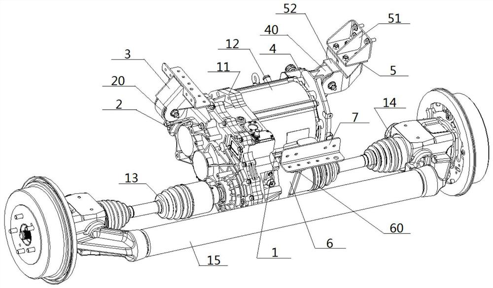
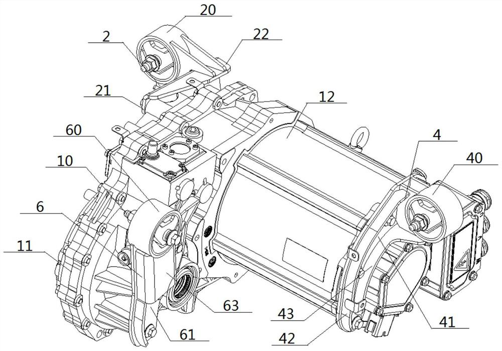
[0071] see figure 1 — Figure 15 , a rear-mounted rear-drive electric vehicle suspension system, comprising a reduction box 11 and a drive motor 12, the right side of the front end of the reduction box 11 is connected with the left end of the drive motor 12, and the rear end of the reduction box 11 on both sides They are respectively connected with the inner ends of the left drive shaft assembly 13 and the right drive shaft assembly 14; the left side of the front end of the reduction box 11 is connected with the left suspension 2, and the connection between the left suspension 2 and the reduction box 11 Opposite to the connection between the drive motor 12 and the reduction box 11, the right end of the drive motor 12 is connected to the right suspension 4, and the rear end of the reduction box 11 is close to the connection between the reduction box 11 and the right drive shaft assembly 14. The parts are connected with the rear suspension 6; the tops of the left suspension 2, ...

Embodiment 2

[0074] The basic content is the same as that of Example 1, except that:

[0075] On hardware:

[0076] The left connection unit 3 is a left connection bracket, the rear connection unit 7 is a rear connection bracket, and the right connection unit 5 includes a right connection bracket 51 and a right transition bracket 52 .

[0077] In the installation method:

[0078] The welding of the left connecting unit 3 and the rear connecting unit 7 to the vehicle frame 8 respectively refers to: welding the left connecting bracket and the rear connecting bracket to the vehicle frame 8 respectively. The bolt connection between the right connecting unit 5 and the frame 8 refers to: bolting the right connecting bracket 51 and the frame 8, tightening the bolts, and then connecting the right transition bracket 52 and the right connecting bracket 51 with bolts without tightening the bolts. .

Embodiment 3

[0080] The basic content is the same as that of Example 1, except that:

[0081] See Figure 14 , the figure shows the pointed bolt 10 used in the bolt connection of the present invention. The pointed bolt 10 includes a nut 101, a screw segment 102, a thread segment 103, and a bolt head 104 connected in sequence. The side of the thread segment 103 An external thread is provided on the enclosure, the top end of the bolt head 104 is connected with the threaded section 103, the bottom end of the bolt head 104 extends outward, and the diameter of the bolt head 104 changes gradually from top to bottom.


PUM


Abstract

The invention discloses a suspension system of a rear-engine rear-drive electric automobile, which comprises a reduction gearbox and a driving motor, wherein the left side of the front end of the reduction gearbox is connected with a left suspension, the joint of the left suspension and the reduction gearbox is opposite to the joint of the driving motor and the reduction gearbox, the right end ofthe driving motor is connected with a right suspension, and the part, which is close to the joint of the reduction gearbox and a right driving shaft assembly, of the rear end of the reduction gearboxis connected with a rear suspension; a left damping module, a right damping module and a rear damping module are correspondingly arranged in the top end of the left suspension, the top end of the right suspension and the top end of the rear suspension respectively, and the left damping module, the right damping module and the rear damping module are connected with a frame through a corresponding left connecting unit, a corresponding right connecting unit and a corresponding rear connecting unit respectively. According to the design, the cost is low, the vibration reduction effect is good, theassembling difficulty is small, and the assembling manufacturability is good.

Description

technical field [0001] The invention relates to a vehicle suspension and its assembling technology, belonging to the field of pure electric vehicles and pure electric vehicle parts, in particular to a suspension system and an installation method of a rear-mounted rear-drive electric vehicle. Background technique [0002] According to the needs of the driving form, the layout of the powertrain is usually arranged in the front cabin and the cockpit, and these two layouts have the form of front-mounted front-wheel drive and rear-mounted rear-wheel drive respectively. When the front-wheel drive is used, the mounting space, structural requirements and installation process requirements of the powertrain are not high, and it is easy to realize. In the electric van, the powertrain is completely under the floor, and the installation space is limited. When the mushroom-shaped cushion is used, it is even more difficult to assemble the powertrain. In addition, the use of casting parts f...

Claims


Application Information

Patent Timeline
Patent Type & Authority Applications(China)
IPC IPC(8): B60K1/00B60K17/06B62D21/11F16F15/08
CPCB60K1/00B60K17/06B62D21/11F16F15/08
Inventor 秦三元赵健生王为才郑兆刚张亮郭良华王浩宇凌帆孙海荣
Owner DONGFENG AUTOMOBILE COMPANY
Why Eureka
Try Eureka