[0030] The present invention will be further described in detail below in conjunction with the accompanying drawings and embodiments. It should be understood that the specific embodiments described herein are only used to explain the present invention, but not to limit the present invention. In addition, it should be noted that, for the convenience of description, the drawings only show some but not all structures related to the present invention.
[0031] In the description of the present invention, unless otherwise expressly specified and limited, the terms "connected", "connected" and "fixed" should be understood in a broad sense, for example, it may be a fixed connection, a detachable connection, or an integrated ; It can be a mechanical connection or an electrical connection; it can be a direct connection or an indirect connection through an intermediate medium, and it can be the internal connection of two elements or the interaction relationship between the two elements. For those of ordinary skill in the art, the specific meanings of the above terms in the present invention can be understood in specific situations.
[0032] In the present invention, unless otherwise expressly specified and limited, a first feature "on" or "under" a second feature may include the first and second features in direct contact, or may include the first and second features Not directly but through additional features between them. Also, the first feature being "above", "over" and "above" the second feature includes the first feature being directly above and obliquely above the second feature, or simply means that the first feature is level higher than the second feature. The first feature is "below", "below" and "below" the second feature includes the first feature is directly below and diagonally below the second feature, or simply means that the first feature has a lower level than the second feature.
[0033] In the description of this embodiment, the terms "upper", "lower", "right", etc. are based on the orientation or positional relationship shown in the accompanying drawings, which are only for convenience of description and simplified operation, rather than indicating Or imply that the device or element referred to must have a particular orientation, be constructed and operate in a particular orientation, and therefore should not be construed as limiting the invention. In addition, the terms "first" and "second" are only used for distinction in description, and have no special meaning.
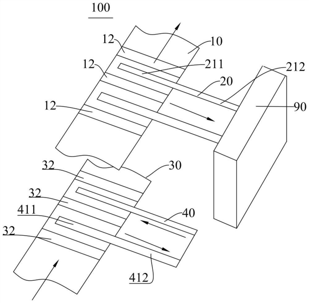
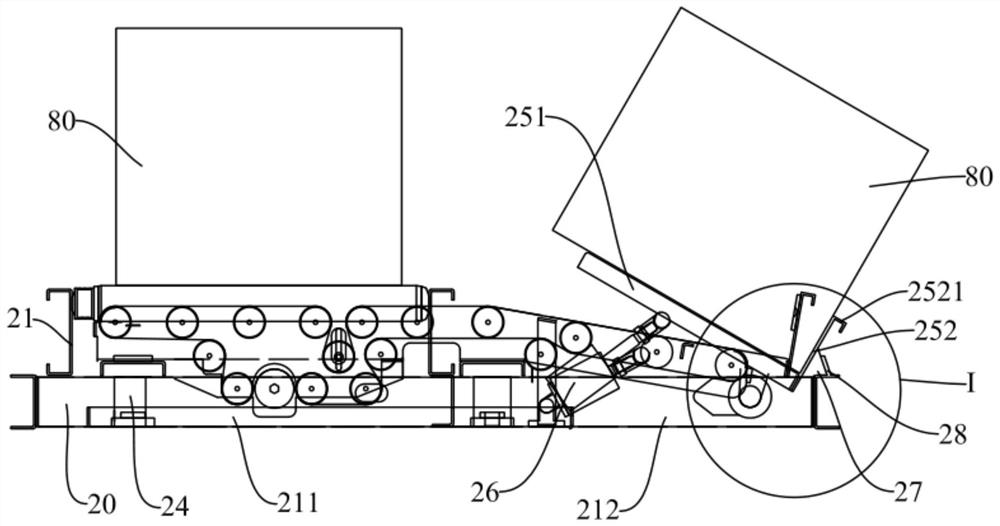
[0034] figure 1 It is a schematic diagram of the logistics sorting device 100 according to the embodiment of the present invention. figure 2 It is a partial side view of the upper sorting mechanism 20 according to the embodiment of the present invention. image 3 is a side view of the upper sorting mechanism 20 according to the embodiment of the present invention, and image 3 The state of the sorting box 80 of the upper sorting mechanism 20 is shown in FIG. Figure 5 It is a top view of the upper conveying mechanism 10 and the upper sorting mechanism 20 according to the embodiment of the present invention.
[0035] like Figure 1-Figure 3 as well as Figure 5As shown, this embodiment discloses a logistics sorting device 100. The logistics sorting device 100 includes an upper conveying mechanism 10 and an upper sorting mechanism 20. The upper conveying mechanism 10 includes a first frame 11 and a The first conveying body 12 on the rack 11 . The upper sorting mechanism 20 includes a second rack 21 , a first height adjustment mechanism 24 , a plurality of first rollers 22 mounted on the second rack 21 , and a first conveyor belt 23 wound around the first rollers 22 , the movable plate 251 and the driving member 26 . The second frame 21 includes a first start section 211 close to the first frame 11 and a first end section 212 away from the first frame 11 , and the first end section 212 is inclined downward. The first conveying belt 23 is arranged at an angle with the conveying direction of the first conveying body 12 . The first height adjustment mechanism 24 is configured to drive the first starting section 211 to ascend and descend, so that the first conveyor belt 23 on the first starting section 211 has a first position lower than the first conveying body 12 and higher than the first conveying body 12 In the second position, when the first conveyor belt 23 is lifted from the first position to the second position, the box body 80 originally on the first conveyor body 12 can be supported and transported to the first end section 212 . The fixed end of the movable plate 251 is hinged to the first end section 212, and the other end is away from the sorting table 90 and is a free end. The first position of the first conveyor belt 23 and the second position of the first conveyor belt 23 higher than the first end section 212, when the free end is lifted from the first position to the second position, the The box body 80 on the first conveyor belt 23 of the segment 212 is supported to change the inclination angle of the box body 80 .
[0036] During the process of conveying several boxes 80 along the first conveying body 12 , the first height adjusting mechanism 24 drives the first starting section 211 of the second frame 21 to rise, so that the first conveyor belt 23 on the first starting section 211 It is higher than the first conveying body 12 , so that the boxes 80 to be sorted are supported and conveyed by the first conveying belt 23 in turn. The boxes 80 are sorted out and move to the sorting table 90 along with the first conveyor belt 23 , so that the staff does not need to search for the boxes 80 with each product in the warehouse, and directly sorts them out on the sorting table 90 The products can be packaged in a centralized manner, thereby improving the sorting efficiency and ultimately improving the logistics transportation efficiency.
[0037] Specifically, the first conveying body 12 is a conveying roller, the number of conveying rollers is several, and the several conveying rollers are distributed at intervals along the extending direction of the first frame 11 . A gap is formed between the adjacent conveyor rollers, so that the first starting section 211 of the second frame 21 can be lifted and lowered through the gap, so that the first conveyor belt 23 on the first starting section 211 is higher than the first conveyor body 12 or lower than the first conveying body 12 . The first starting section 211 includes two frame bodies arranged at intervals, and the two frame bodies can be lifted up from the two gaps respectively.
[0038] When the first conveyor belt 23 on the first starting section 211 is higher than the first conveyor body 12 , the box 80 originally on the first conveyor body 12 can be supported by the first conveyor belt 23 instead. Driven by the motor, the first conveyor belt 23 transports the box 80 to the sorting table 90 .
[0039] When the first conveyor belt 23 on the first starting section 211 is lower than the first conveyor body 12 , the box 80 continues to be transported by the first conveyor body 12 .
[0040] Therefore, under the control of the control system, after the upper sorting mechanism 20 sorts a box 80 on the upper conveying mechanism 10, the first starting section 211 of the second rack 21 needs to be driven by the first height adjusting mechanism 24 Descending until the first conveyor belt 23 on the first starting section 211 is lower than the first conveyor body 12 , so that the first conveyor body 12 can continue to convey other boxes 80 .
[0041] The first height adjustment mechanism 24 in this embodiment can be a lift cylinder, which can be fixed on the first frame 11 , and the telescopic rod of the lift cylinder is fixedly connected to the first starting section 211 of the second frame 21 . The lift cylinder can be arranged perpendicular to the first frame 11 . The lift cylinder may be installed at the starting end of the first starting section 211 of the second frame 21 . The starting end of the first starting section 211 refers to the end facing away from the sorting table 90 .
[0042] like figure 1 and figure 2 As shown in the figure, the second frame 21 of this embodiment is divided into two parts, wherein the part whose projection in the vertical direction overlaps with the first frame 11 is the above-mentioned first starting section 211, and the rest part, that is, the part close to the part The part of the picking table 90 is the first end section 212 of the second rack 21 . The first end section 212 of the second rack 21 in this embodiment extends to the sorting table 90 .
[0043] In this embodiment, the first starting section 211 of the second rack 21 is arranged in parallel with the first rack 11 in a state of not rising, and the first end section 212 of the second rack 21 is parallel to the first rack 21 of the second rack 21 . An angle is formed between the first starting sections 211, and the height of the first end section 212 of the second rack 21 gradually decreases in the direction close to the sorting table 90, which facilitates the transportation of the boxes 80 containing products to the sorting work Station 90.
[0044] The upper sorting mechanism 20 of this embodiment is mainly used to sort out computer assembly parts. After sorting out the at least two parts to be assembled, the staff assembles the at least two parts to be assembled on the sorting table 90 . together, and then package and send. The workers can transfer the packaged products to the lower conveying mechanism 30 through the lower sorting mechanism 40 hereinafter, and then convey the packaged products out.
[0045] Preferably, in the axial direction, the outer peripheral surface of the first roller 22 is a circular arc surface with a high center portion and two low sides. The outer peripheral surface of the existing roller is a standard cylindrical surface, and the outer peripheral surface of the first roller 22 in this embodiment is an arc surface in the axial direction, and has the highest height in the middle. The structure of the first roller 22 in this embodiment is beneficial to prevent the first conveyor belt 23 from deviating, thereby saving the time for adjusting the first conveyor belt 23, so that the upper sorting mechanism 20 in this embodiment can continue to work for a long time. It is beneficial to improve the efficiency of logistics transportation.
[0046] Figure 4 Yes image 3 Partial enlargement at I. like image 3 and Figure 4 As shown, preferably, the fixed end of the movable plate 251 is hinged to the end of the second frame 21 . When the box body 80 enters the first end section 212 of the second frame 21 from the first starting section 211 of the second frame 21 and reaches above the movable plate 251, the driving member 26 drives the free end of the movable plate 251 to rise, to support the box body 80 . In this embodiment, the function of driving the free end of the movable plate 251 to rise by the driving member 26 is to change the angle between the box body 80 containing the products and the sorting table 90, so that the staff can easily see the contents in the box body 80. products, and it is convenient for the staff to take the products in the box 80 .
[0047] In this embodiment, the first end section 212 is inclined downward, so that when the free end of the movable plate 251 moves upward to touch the box body 80, the inclination angle of the first end section 212 and the movable plate 251 is closer. The box body 80 is easy to move to the movable plate 251 , and the box body 80 is not easily overturned during the process that the free end of the movable plate 251 continues to move upward for a certain distance to fully support the box body 80 . The inclined arrangement of the first end section 212 of the second frame 21 and the installation structure between the movable plate 251 and the first end section 212 in this embodiment can improve the stability of the transport box 80 , thereby facilitating the improvement of logistics transportation. efficiency.
[0048] Preferably, a baffle plate 252 is further connected to the fixed end of the movable plate 251 , and the movable plate 251 and the baffle plate 252 enclose an accommodation space for accommodating the box body 80 . The general box body 80 has a cube-shaped structure, and the movable plate 251 and the baffle plate 252 of this embodiment are perpendicular to each other to match the shape of the box body 80 . The baffle 252 is used to limit the box body 80 to prevent the box body 80 from tipping over.
[0049] Preferably, the free end of the baffle plate 252 is bent away from the accommodating space to form a hook portion 2521 . The hook portion 2521 can facilitate the installation of the baffle plate 252 by the staff and improve the strength of the free end of the baffle plate 252 .
[0050] Preferably, the upper sorting mechanism 20 further includes a sloping plate 28 connected to the first end section 212 , a shock absorbing body 27 is injected into the space enclosed by the sloping plate 28 and the first end section 212 , and the cross-sectional shape of the shock absorbing body 27 is It is a triangle, and its apex is higher than the inclined plate 28 . When the box 80 slides from the free end of the movable plate 251 to the baffle 252 along the movable plate 251, it is easy to produce a certain impact force on the baffle 252, and a long-term impact is likely to cause the movable plate 251 and the baffle 252 to interact with each other. The connection between the first end sections 212 is loose. The shock absorbing body 27 in this embodiment is simple in molding method and simple in structure, and can play a good role in shock absorption, so that the movable plate 251 and the baffle 252 can work for a long time, which is beneficial to save maintenance time and improve the efficiency of logistics transportation.
[0051] like figure 2 As shown, preferably, a first tensioning mechanism 29 is provided between two adjacent first rollers 22 on the first starting section 211, and the tensioning wheel of the first tensioning mechanism 29 is connected to the first conveyor belt 23 of the top layer. Cooperate. The existing tensioning mechanism is generally set at the starting end of the first starting section 211, the first tensioning mechanism 29 in this embodiment is set at the middle position of the first starting section 211, install the first tensioning mechanism 29 and adjust the tensioning The wheels are more convenient and the tensioning effect is good.
[0052] Image 6 It is a side view of the lower sorting mechanism 40 according to the embodiment of the present invention. Figure 7 It is a top view of the lower conveying mechanism 30 and the lower sorting mechanism 40 according to the embodiment of the present invention. like figure 1 , Image 6 and Figure 7 As shown, preferably, the logistics sorting device 100 of this embodiment further includes a lower conveying mechanism 30 and a lower sorting mechanism 40 , and the lower conveying mechanism 30 includes a third frame 31 and a third frame mounted on the third frame 31 . The conveying body 32 and the lower sorting mechanism 40 are used to sort the boxes 80 on the third conveying body 32 . The lower conveying mechanism 30 is located directly below the upper conveying mechanism 10 , and the lower sorting mechanism 40 is located at one side of the upper sorting mechanism 20 .
[0053] The logistics sorting device 100 of this embodiment includes both the upper conveying mechanism 10 and the lower conveying mechanism 30, thereby improving the utilization rate of space in the workshop, and simultaneously transporting multiple boxes 80, thereby improving the transportation efficiency.
[0054] The lower sorting mechanism 40 of this embodiment can be transported in both directions, it can not only sort out the boxes 80 on the lower conveying mechanism 30, but also can pack the packaged products into the boxes 80, and then re-transport to the lower conveying mechanism 30.
[0055] The lower-level sorting mechanism 40 and the upper-level sorting mechanism 20 in this embodiment can cooperate with each other to improve the logistics conveying efficiency. For example, after packing the products sorted by the upper sorting mechanism 20 , the workers put them into the box 80 on the lower sorting mechanism 40 , and transport the box 80 to the lower conveying mechanism 30 through the lower sorting mechanism 40 . , and then the packaged products are transported away through the lower conveying mechanism 30 .
[0056] Preferably, the lower sorting mechanism 40 includes a fourth rack 41 , a second height adjustment mechanism 44 , a plurality of second rollers 42 mounted on the fourth rack 41 and a second roller 42 wound around the plurality of second rollers 42 . The conveyor belts 43 and the fourth frame 41 and the third frame 31 extend in different directions. Both the second starting section 411 and the second ending section 412 of the fourth frame 41 are provided with a second height adjusting mechanism 44 .
[0057] Specifically, the extending direction of the third frame 31 in this embodiment is parallel to the extending direction of the first frame 11 . The extending direction of the fourth frame 41 is parallel to the extending direction of the second frame 21 . The second rack 21 is perpendicular to the first rack 11 , and correspondingly, the fourth rack 41 is perpendicular to the third rack 31 .
[0058]The third conveying body 32 in this embodiment is a conveying roller, the number of conveying rollers is several, and the several conveying rollers are distributed at intervals along the extending direction of the third frame 31 . A gap is formed between adjacent conveying rollers, so that the second starting section 411 of the fourth frame 41 can be lifted and lowered through the gap, thereby enabling the second conveying on the second starting section 411 of the fourth frame 41 The belt 43 is higher than the third conveying body 32 or lower than the third conveying body 32 .
[0059] When the second conveyor belt 43 on the second initial section 411 of the fourth rack 41 is higher than the third conveyor body 32 , the box 80 containing the products originally on the third conveyor body 32 can be turned to be The second conveyor belt 43 is supported. Driven by the motor, the second conveyor belt 43 transports the box 80 to the second end section 412 of the fourth frame 41 . The second end section 412 is close to the sorting table 90 to facilitate the staff to pack products.
[0060] The second height adjusting mechanism 44 drives the second starting section 411 of the fourth frame 41 to descend until the second conveyor belt 43 on the second starting section 411 of the fourth frame 41 is lower than the third conveying body 32 , so that The third conveying body 32 normally transports the product.
[0061] After the products are packed, the motor of the second conveyor belt 43 rotates in the reverse direction, the second conveyor belt 43 is transported in the reverse direction, and the box 80 containing the packaged products is transported to the third conveyor body 32, The box 80 containing the packaged product is transported away.
[0062] Preferably, the second height adjustment mechanism 44 is an eccentric wheel mechanism, and a damping mechanism is provided between the eccentric wheel mechanism and the fourth frame 41 . The eccentric wheel of the eccentric wheel mechanism is driven by the motor to rotate. The second initial section 411 and the second final section 412 of the fourth frame 41 are driven up and down by the eccentrics below them.
[0063] The second roller 42 is the same as the first roller 22. In the axial direction, the outer peripheral surface of the second roller 42 is a circular arc surface with a high middle portion and a low side portion. The structure of the second roller 42 in this embodiment is beneficial to prevent the second conveyor belt 43 from deviating, thereby saving the time for adjusting the second conveyor belt 43, so that the lower sorting mechanism 40 in this embodiment can continue to work for a long time. It is beneficial to improve the efficiency of logistics transportation.
[0064] A second tensioning mechanism 49 is provided between two adjacent second rollers 42 . The tensioning pulley of the second tensioning mechanism 49 is in tension with the second conveyor belt 43 located on the upper layer. When the second conveyor belt 43 is loose, the tension of the second conveyor belt 43 is adjusted by adjusting the position of the tensioning pulley of the second tensioning mechanism 49 . The first tensioning mechanism 29 and the second tensioning mechanism 49 in this embodiment are both arranged at positions that are convenient for the staff to adjust.
[0065] Obviously, the above-mentioned embodiments of the present invention are only examples for clearly illustrating the present invention, rather than limiting the embodiments of the present invention. For those of ordinary skill in the art, various obvious changes, readjustments and substitutions can be made without departing from the protection scope of the present invention. There is no need and cannot be exhaustive of all implementations here. Any modifications, equivalent replacements and improvements made within the spirit and principle of the present invention shall be included within the protection scope of the claims of the present invention.