Sweeping roller structure for road maintenance and sweeper

A technology for road maintenance and cleaning rollers, applied in road cleaning, cleaning methods, construction, etc., can solve the problems of increasing operating strength, inconvenient disassembly and assembly, and increasing costs, and achieve the effect of preventing pollution

Inactive Publication Date: 2020-11-06
王宏
View PDF8 Cites 3 Cited by
  • Summary
  • Abstract
  • Description
  • Claims
  • Application Information

AI Technical Summary

Problems solved by technology

[0006] There are also sweepers that use horizontal sweeping rollers to clean the road surface. Due to the different road conditions, some brushes on the sweeping roller will wear away with the stones on the road surface, causing this part of the brushes to fall off in advance. It is inconvenient to clean the brush after cleaning the floor. If it is not replaced, it will affect the next use. During the replacement process, the traditional cleaning roller and the brush are fixedly installed, which is not easy to disassemble. Therefore, when replacing Requires sweeper rolls to be replaced together, increasing cost and increasing operational intensity

Method used


Image

  • Sweeping roller structure for road maintenance and sweeper
  • Sweeping roller structure for road maintenance and sweeper
  • Sweeping roller structure for road maintenance and sweeper

Examples


Embodiment 1

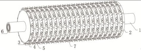
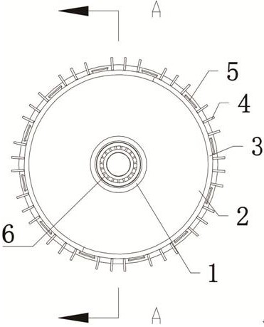
[0034] Reference attached Figure 1~Figure 6 , a cleaning roller for highway maintenance, comprising a cleaning roller body 2 equidistantly provided with a plurality of arc-shaped grooves on the circumferential surface, the cleaning roller body 2 is fixedly mounted on a transmission roller 1, and the transmission roller 1 is a In the shape of a stepped hollow shaft, the cleaning roller body 2 is installed at the maximum diameter of the transmission roller 1, and a plurality of drainage holes 7 pointing to the inside of the transmission roller 1 are provided on the part of the circumference of the cleaning roller body 2 other than the arc groove. Brush mounting plates 3 are movably installed in the arc-shaped grooves of the cleaning roller body 2 through screws 5 respectively, and a plurality of brushes 4 are respectively mounted on the brush mounting plates 3 . Compared with the prior art, the present invention adopts the brush mounting plate which is movably installed on the ...

Embodiment 2

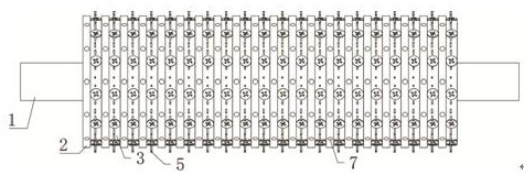
[0043] Reference attached Figure 7 , a cleaning vehicle for road maintenance, including a vehicle body, and also includes the cleaning roller for road maintenance as described in the above embodiments.

[0044] In this embodiment, the car body includes a housing 8, and two groups of driving wheels 9 are installed in parallel at the lower part of the housing 8, and each group of driving wheels 9 is two driving wheels 9 connected coaxially. The lower part of the body 8 is located between the two groups of driving wheels 9, and a cleaning roller body 2 is also installed. The driving roller 1 on the cleaning roller body 2 is installed on the housing 8 through an external bearing, and the driving roller 1 is connected with a belt transmission mechanism 13. The drive shaft of the driving motor 14 fixedly installed on the inner top of the housing 8 maintains the power output.

[0045] In this embodiment, a water tank 10 is fixedly placed on one side of the housing 8, and a garbage ...


PUM


Abstract

The invention discloses a sweeping roller structure for road maintenance and a sweeper. The sweeping roller structure comprises a cleaning roller body with a plurality of arc-shaped grooves formed inthe circumferential surface at equal intervals. The cleaning roller body is fixedly installed on a transmission roller. The transmission roller is in the shape of a stepped hollow shaft; the cleaningroller body is mounted at the maximum diameter of the transmission roller; a plurality of drainage holes pointing to the interior of the transmission roller are formed in the circumferential portion,except for the arc-shaped grooves, of the cleaning roller body, brush installation plates are movably installed in the arc-shaped grooves of the cleaning roller body through screws, and a plurality ofbrushes are installed on the brush installation plates. According to the sweeping roller, the brushes can be replaced at will, and the situation that after the brushes make contact with the ground for a long time, the brushes fall excessively, and consequently sweeping quality is reduced is prevented.

Description

technical field [0001] The invention relates to the technical field of environmental protection equipment, in particular to a cleaning roller structure for road maintenance and a cleaning vehicle. Background technique [0002] The existing cleaning equipment used for road maintenance generally has two types: minicomputer and mainframe. The minicomputer needs to manually push the cleaning machine forward, and use the cleaning roller to clean it. In the warehouse, the work intensity is high, the efficiency is low, and it is impossible to clean the particulate matter. The large-scale cleaning machines have high power and good effect, but most of them are imported machines, which are expensive and noisy, and cannot clean the particulate matter, which is not conducive to popularization and use. . After searching, it is found that the invention of patent No. CN201810727721.0 discloses a road maintenance construction engineering vehicle for road maintenance construction, including...

Claims


Application Information

Patent Timeline
Patent Type & Authority Applications(China)
IPC IPC(8): E01H1/05E01H1/04
CPCE01H1/056E01H1/042
Inventor 王宏陶文超韩建杰马文霞
Owner 王宏
Why Eureka
Try Eureka