Auxiliary mounting device for indoor decoration

An installation device and interior decoration technology, applied in the direction of architecture, building structure, etc., can solve problems such as low efficiency, hidden dangers, and cumbersome installation process, and achieve the effect of improving production efficiency and reducing hidden dangers.

Active Publication Date: 2020-11-06
山东智汇新谷科技企业孵化器有限公司
View PDF10 Cites 1 Cited by
  • Summary
  • Abstract
  • Description
  • Claims
  • Application Information

AI Technical Summary

Problems solved by technology

[0005] In order to overcome the prior art, the present invention needs to turn holes on the wall body first, then embed wooden plugs in the punched holes in the prior art, and then nail the buckles to the pre-embedded holes with a steel nail gun. Then install the baseboard on the cork. The installation process is cumbersome and requires a

Method used


Image

  • Auxiliary mounting device for indoor decoration
  • Auxiliary mounting device for indoor decoration
  • Auxiliary mounting device for indoor decoration

Examples


Embodiment

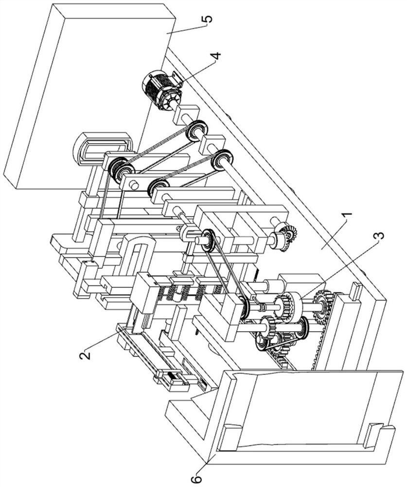
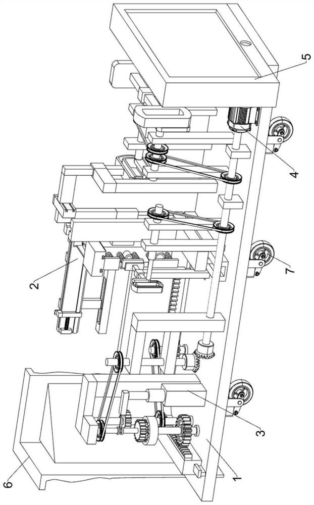
[0033] An interior decoration auxiliary installation device such as Figure 1-10 As shown, it includes a chassis 1, a buckle pre-installation mechanism 2, a corner gusset plate installation mechanism 3, a baseboard buckle mechanism 4, a control panel 5, a right-angle buckle 6 and an electric wheel 7; Corner gusset plate installation mechanism 3, buckle pre-installation mechanism 2, skirting line pressing mechanism 4 and control panel 5; bottom frame 1 is provided with electric wheels 7; buckle pre-installation mechanism 2 and skirting line pressing mechanism 4 phases are connected;

[0034] When in use, first place the device on the wall, and then manipulate the control panel 5 to control the electric wheel 7 to drive the device to move along the wall. When it moves to one-third of the wall, the electric wheel 7 stops moving, and then the buckle The pre-installation mechanism 2 first drills a small hole on the wall, then inserts the wooden plug into the drilled small hole, th...


PUM


Abstract

The invention relates to the field of indoor decoration, in particular to an auxiliary mounting device for indoor decoration. The technical problem to be solved by the invention is to provide the auxiliary mounting device for indoor decoration. The auxiliary mounting device for indoor decoration comprises a bottom frame, a buckle pre-installation mechanism, a corner buckle plate installation mechanism, a skirting line pressing buckle mechanism, a control screen, a right-angle pressing buckle and electric wheels, and the electric wheels are arranged above and below the bottom frame. When the auxiliary mounting device is used, automatic drilling on a wall surface is achieved, a wooden plug is automatically embedded into a drilled hole, then a buckle is automatically fixed to the wooden plug,then a PVC skirting line is automatically clamped into the right-angle pressing buckle of a wall corner, and then the PVC skirting line is automatically clamped into an installed pressing buckle; andduring use, a worker only needs to place the PVC skirting line at a wall corner without operating a steel nail gun, so that the production efficiency is improved, and the potential safety hazard is greatly reduced.

Description


Claims


Application Information

Patent Timeline
Owner 山东智汇新谷科技企业孵化器有限公司
Why Eureka
Try Eureka