
Safe locking device for rotary blowout preventer and locking method

A technology of rotating blowout preventer and safety locking, which is applied in earthwork drilling, wellbore/well components, sealing/isolation, etc., and can solve the problem of screw hole loading and unloading of corroded safety bolts, safety bolts, operating tools falling into wells, and operators Falls and other problems, to improve the safety and efficiency of work, easy and flexible to open and engage, increase safety and reliability

Pending Publication Date: 2020-11-06
BC P INC CHINA NAT PETROLEUM CORP +1
View PDF0 Cites 0 Cited by
  • Summary
  • Abstract
  • Description
  • Claims
  • Application Information

AI Technical Summary

Problems solved by technology

[0010] The purpose of the present invention is to overcome the deficiencies of the above-mentioned prior art, and provide a safety locking device and locking method for a rotary blowout preventer, which overcomes 1 in the prior art: the installer must carry tools such as a large adjustable wrench, safety bolts, etc. , the installers work at heights, the station space is limited, the bolt rotation angle is too small, the installation and disassembly procedures are complicated and inefficient; 2: The safety risk of the installers is high, the installers need to work at heights, and the station space is limited, so they can only use one hand 3: There is a risk of safety bolts and operating tools falling into the well, causing complicated underground accidents; 4: The mud is easy to block, and the screw holes of the safety bolts are corroded, which makes loading and unloading difficult, etc.

Method used


Image

  • Safe locking device for rotary blowout preventer and locking method
  • Safe locking device for rotary blowout preventer and locking method
  • Safe locking device for rotary blowout preventer and locking method

Examples


specific Embodiment approach

[0046] It should be noted that the structures, proportions, sizes, etc. shown in this specification are only used to cooperate with the content disclosed in the specification for the understanding and reading of those familiar with this technology, and are not used to limit the conditions for the implementation of the present invention , any modification of structure, change of proportional relationship or adjustment of size shall still fall within the scope covered by the technical content disclosed in the present invention without affecting the effect and purpose of the present invention. .

[0047] At the same time, terms such as "upper", "lower", "left", "right", "middle" and "one" quoted in this specification are only for the convenience of description and are not used to limit this specification. The practicable scope of the invention and the change or adjustment of its relative relationship shall also be regarded as the practicable scope of the present invention without...

Embodiment 1

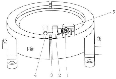
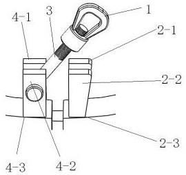
[0049] like figure 1 As shown, the present invention discloses a safety locking device for a rotary blowout preventer, including a safety pin, a pin holder and a self-locking device 5, the safety pin includes a big lug nut 1 and a pin screw 3, and the pin The pin clamp includes a first pin clamp 2 and a second pin clamp 4, the first pin clamp 2 is fixed on the top opening side of the rotating BOP shell clamp, and the second pin clamp 4 is fixed on the other side of the opening top of the clamp of the rotating BOP shell, one end of the pin screw 3 is rotatably fixed on the second pin holder 4, and the other end of the pin screw 3 is connected to the big lug nut 1, wherein The big lug nut 1 can be locked on the first pin holder 2, the self-locking device 5 is fixed on the top of the hoop of the rotating BOP housing and the self-locking device 5 and the first pin holder 2 are arranged in a rotating At the opening on the same side of the BOP shell clamp, the self-locking device 5...

Embodiment 2

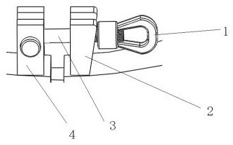
[0051] preferred, such as Figure 1~3 As shown, the big lug nut 1 includes a threaded buckle and ear-shaped earrings, wherein the two sides of one end surface of the threaded buckle are respectively connected with the ear-shaped earrings, the inner wall of the threaded buckle is provided with threads, and the threaded buckle is threadedly connected with the pin screw rod 3 .

[0052] Described threaded thread can be threadedly connected with pin bolt screw rod 3, adjusts the thread pitch by rotating threaded thread.

[0053] Preferably, one end of the pin screw 3 is rotatably fixed on the second pin holder 4, wherein the other end surface of the pin screw 3 is provided with threads, wherein the surface threads of the pin screw 3 are threaded with the screw thread of the big lug nut 1 Compatible with internal thread.

[0054] The size of the ear-shaped earrings of the big lug nut 1 in the axial direction of the pin bolt screw 3 is greater than the thread size of the pin bolt s...


PUM


Abstract

The invention discloses a safe locking device for a rotary blowout preventer and a locking method. The safe locking device comprises a safe bolt pin, a bolt pin deck and a self-locking device (5). Thesafe bolt pin comprises a large lug nut (1) and a bolt pin screw (3). The bolt pin deck comprises a first bolt pin deck body (2) and a second bolt pin deck body (4). The first bolt pin deck body (2)is fixed to one side of an opening in the top of a shell clamp of the rotary blowout preventer, the second bolt pin deck body (4) is fixed to the other side of the top of the opening of the shell clamp of the rotary blowout preventer, one end of the bolt pin screw (3) is rotationally fixed to the second bolt pin deck body (4), the other end of the bolt pin screw (3) is connected with the large lugnut (1), the large lug nut (1) can be locked on the first bolt pin deck body (2), the self-locking device (5) is fixed to the top of the shell clamp of the rotary blowout preventer, the self-lockingdevice and the first bolt pin deck body are arranged at the positions of the opening in the same side of the shell clamp of the rotary blowout preventer, and the self-locking device can be clamped into the large lug nut.

Description

technical field [0001] The invention belongs to the technical field of locking of a rotating blowout preventer, and in particular relates to a safety locking device and a locking method for a rotating blowout preventer. Background technique [0002] The existing "three low" oil reservoirs have low initial reservoir pressure, and it is necessary to increase the reservoir capacity through water injection to achieve the purpose of efficient production. Long-term water injection production has led to abnormal pressure in some reservoirs. During drilling and completion, problems such as overflow (water, oil, associated gas) and co-existence of spills and leakages are prone to occur. The risk of well control and operation difficulty increase. The pressure drilling technology adopts the rotary blowout preventer system, which effectively reduces the drilling control risk and operation difficulty. It has become the main drilling technology for oilfield development in high-pressure wa...

Claims


Application Information

Patent Timeline
Patent Type & Authority Applications(China)
IPC IPC(8): E21B33/06
CPCE21B33/06
Inventor 彭元超谢新刚李欣胡东峰陈小荣杨赟仵磊王玉韩朝辉周雄兵李晓黎杨茂红高峰刘志雄刘立鹏吴光肖凯
Owner BC P INC CHINA NAT PETROLEUM CORP
Learn More