
Surface defect detection device and method

A defect detection and defect technology, applied in measurement devices, optical testing defects/defects, image data processing, etc., can solve the problem of high missed detection rate, and achieve the effect of reducing costs, reducing errors, and improving economic benefits of enterprises

Pending Publication Date: 2020-11-06
GUANGXI NORMAL UNIV
View PDF13 Cites 12 Cited by
  • Summary
  • Abstract
  • Description
  • Claims
  • Application Information

AI Technical Summary

Problems solved by technology

[0004] In order to overcome the defects of high missed detection rate of existing surface defect detection devices, the present invention provides a surface defect detection device and method

Method used


Image

  • Surface defect detection device and method
  • Surface defect detection device and method
  • Surface defect detection device and method

Examples


Embodiment Construction

[0067] In order to make the purpose, technical solutions and advantages of the present invention more clear, the present invention will be further described in detail below in conjunction with the accompanying drawings and implementation examples. It should be understood that the specific embodiments described here are only used to explain the present invention, not to limit the present invention.

[0068] It should be noted that when an element is referred to as being “fixed” to another element, it can be directly on the other element or there can also be an intervening element. When an element is referred to as being "connected to" another element, it can be directly connected to the other element or intervening elements may also be present. The terms "vertical," "horizontal," "left," "right," and similar expressions are used herein for purposes of illustration only.

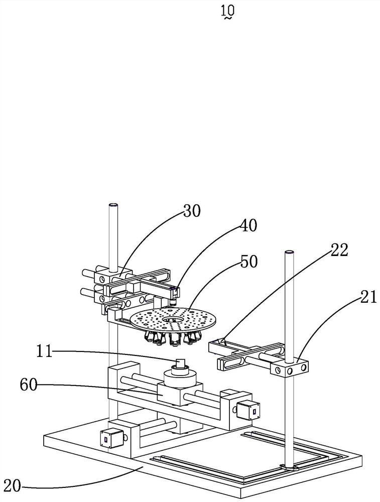
[0069] see figure 1 , the present invention provides a surface defect detection device 10, the surface de...


PUM


Abstract

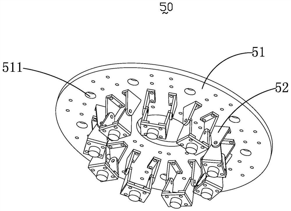
The invention relates to the technical field of computer vision, and particularly relates to a surface defect detection device. The device comprises a platform, an object carrying assembly arranged onthe platform, a first support, a camera and light source assembly connected with the first support, a second support and a coaxial light source connected with the second support. The first support and the second support are oppositely arranged on the platform. The object carrying assembly is located in a shooting area of the camera and is used for carrying a to-be-detected sample; the light source assembly comprises nine light-emitting assemblies capable of emitting light independently or simultaneously, the light-emitting assemblies are opposite to the sample to be detected and arranged between the camera and the sample to be detected so as to provide an LED light source, and the coaxial light source obliquely irradiates the sample to be detected so as to provide a coaxial light source.A surface defect detection method is provided. The surface defect detection device has the advantages of being high in efficiency, low in false detection rate and omission ratio and the like, and themethod has the advantages of being high in three-dimensional reconstruction speed and three-dimensional reconstruction precision, improving defect detection capacity and the like.

Description

【Technical field】 [0001] The invention relates to the technical field of detection equipment, in particular to a surface defect detection device and method. 【Background technique】 [0002] At present, the detection technology for metal surface defects is relatively immature, and the detection rate for rough texture metal surface defects is extremely low, and the false detection rate and missed detection rate are extremely high. [0003] At present, there is a vision-based surface fine defect detection technology on the market. This technology collects 4 images of the metal surface to be tested at different illumination angles through 4 red-light point light source image systems, and uses the calibrated light source direction parameters. Calculate the gray value gradient of the object, and at the same time perform Gaussian curvature filter processing on the gray value gradient, synthesize the curvature image, and then perform image segmentation and morphological operations to...

Claims


Application Information

Patent Timeline
IPC IPC(8): G01N21/88G06T7/00G06T7/10G06T7/41G06T7/90G06T5/00G06T5/20
CPCG01N21/8806G01N21/8851G06T7/0008G06T7/10G06T7/41G06T7/90G06T5/20G01N2021/8809G01N2021/8835G01N2021/8887G01N2201/062G06T2207/10004G06T2207/10024G06T2207/30136G06T5/70
Inventor 朱勇建罗坚刘浩张力秦运柏秦国锋
Owner GUANGXI NORMAL UNIV
Learn More