
A groundwater flow performance detection device and detection method

A technology of flow performance and detection device, which is applied in the direction of measurement device, fluid velocity measurement, indicating/recording action, etc., can solve the problems of large workload, long construction period, cumbersome process, etc., and achieves simple structure, high accuracy, and detection method. Convenient and fast effects

Active Publication Date: 2021-12-17
CHINA PETROLEUM & CHEM CORP +1
View PDF10 Cites 0 Cited by
  • Summary
  • Abstract
  • Description
  • Claims
  • Application Information

AI Technical Summary

Problems solved by technology

This method has a large workload, long construction period and cumbersome process

Method used


Image

  • A groundwater flow performance detection device and detection method
  • A groundwater flow performance detection device and detection method
  • A groundwater flow performance detection device and detection method

Examples


Embodiment 1

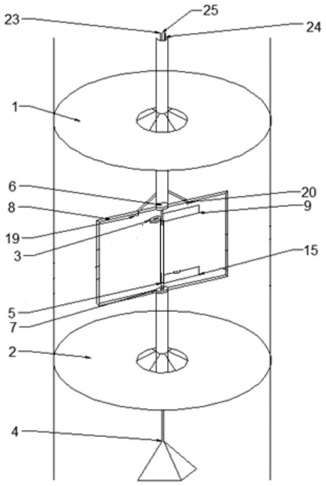
[0052] Please refer to figure 1 , the present embodiment provides a groundwater flow performance detection device and detection method, the groundwater flow performance detection device includes a first mounting part 8, a direction indicator 3, a deflector, an ultraviolet light source 19 and a camera 20. The two vertical lines on the left and right in the figure represent a single wellbore.

[0053] The deflection element is connected to the first mounting element and used for deflection under the action of water flow.

[0054] The direction indicating member 3 is disposed on the first installation member 8 and the indicating direction of the direction indicating member 3 remains unchanged all the time. In an optional embodiment, the direction indicator 3 may be a compass. The needle of the compass has fluorescent markings to indicate the direction of true north during the measurement.

[0055] By setting the direction indicator 3 and the deflector with fluorescent marks, t...

Embodiment 2

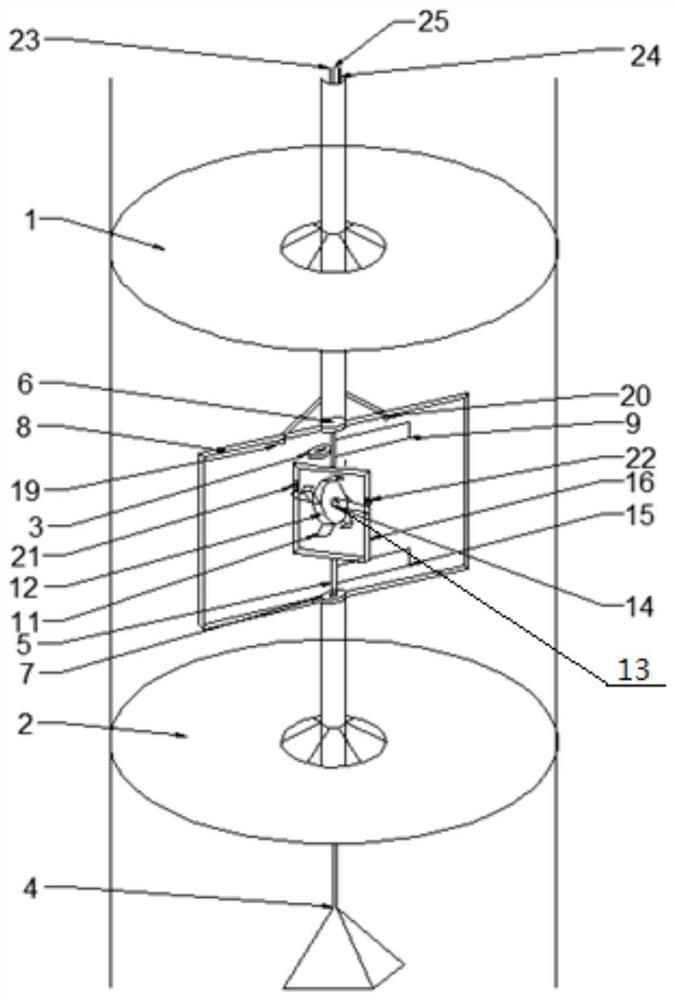
[0084] Please refer to figure 2 , the present embodiment provides a groundwater flow performance detection device and measurement method, the groundwater flow performance detection device on the basis of embodiment 1 has increased the second mounting part 16, lateral rotation shaft 13, runner 12 and rotational speed measuring device .

[0085] The second mounting part 16 is fixedly connected to the vertical rotating shaft 5 , and it can rotate together with the vertical rotating shaft 5 .

[0086] For reference, the second mounting member 16 may be in the shape of a frame, and the frame may be in the shape of a rectangle, a square, a circle, or a rhombus. In this embodiment, a rectangular frame is taken as an example, which includes an upper border and left and right borders. Both ends of the horizontal rotation shaft 13 are connected to the second mounting member 16, specifically, connected to the left frame and the right frame respectively. Preferably, the lateral rotati...


PUM


Abstract

The application provides a groundwater flow performance testing device and a testing method, which belong to the technical field of groundwater testing. The detection device includes a first mounting part, a direction indicating part, a deflecting part, an ultraviolet light source and an imaging part; the deflecting part is connected to the first mounting part and is used for deflecting under the action of water flow; the direction indicating part is arranged on the first mounting part and The direction indicated by the direction indicator remains unchanged; both the direction indicator and the deflector have fluorescent marks; the ultraviolet light source and the camera are arranged on the first mounting part, and the camera is used to record the position of the direction indicator and the deflector and The flow direction of the groundwater to be measured is measured by the angle between the direction indicator and the deflector when the deflector is rotated to be parallel to the flow direction of the groundwater to be measured. The detection device has a simple structure, a convenient and rapid detection method, no complicated calculation is required, and no radioactive elements or other tracers need to be added separately during the measurement process.

Description

technical field [0001] The invention relates to the field of groundwater detection, in particular to a groundwater flow performance detection device and detection method. Background technique [0002] Groundwater seepage velocity and flow direction are not only two important dynamic parameters in the study of groundwater seepage field, but also the main parameters for determining hydrogeological parameters such as aquifer permeability coefficient and seepage flow. The traditional method of measuring groundwater flow velocity and flow direction is to arrange boreholes along the flow direction on the basis of understanding the geological conditions of the studied area and the approximate groundwater flow direction, and then measure the groundwater flow velocity through pumping tests. The method has a large workload, a long construction period, and complicated processes. [0003] In view of this, the present application is proposed. Contents of the invention [0004] One of...

Claims


Application Information

Patent Timeline
Patent Type & Authority Patents(China)
IPC IPC(8): G01P5/18G01P13/04
CPCG01P5/18G01P13/045
Inventor 白正伟王乾贾苒李怿李磊王飞龙李翔蔡凌霄金欣
Owner CHINA PETROLEUM & CHEM CORP
Learn More