fixed focus lens

A fixed-focus lens and lens technology, applied in the field of fixed-focus lenses, can solve the problems of reduced image peripheral clarity and brightness, unused pixels around the chip, and large impact on image quality, achieving small distortion, reduced weight and cost, low weight effect

Active Publication Date: 2022-04-29
JIANGXI LIANCHUANG ELECTRONICS CO LTD
View PDF3 Cites 0 Cited by
  • Summary
  • Abstract
  • Description
  • Claims
  • Application Information

AI Technical Summary

Problems solved by technology

Although this method of stretching the image can solve the problem of image distortion caused by distortion, the image quality will be greatly affected by the large stretching changes, such as the sharpness and brightness of the image around the image will be reduced, and it cannot solve the problem of a part of the chip around the chip. The problem with unused pixels

Method used


Image

  • fixed focus lens
  • fixed focus lens
  • fixed focus lens

Examples


no. 1 example

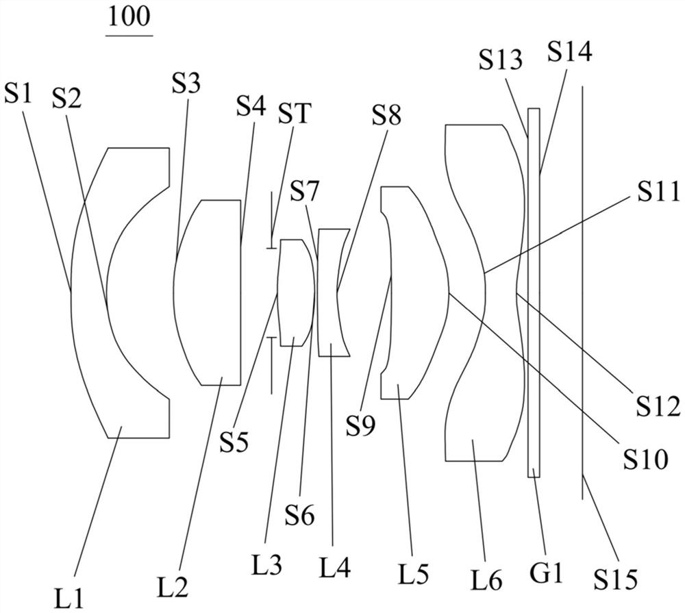
[0099] see figure 1 , which is a structural diagram of the fixed-focus lens 100 provided in the first embodiment of the present invention. The fixed-focus lens 100 includes a first lens L1, a second lens L2, a stop ST, and a third lens L3 in order from the object side to the imaging surface. , the fourth lens L4, the fifth lens L5, the sixth lens L6 and the filter G1.

[0100] The first lens L1 has negative refractive power, the object side S1 of the first lens is convex, and the image side S2 is concave; the second lens L2 has positive refractive power, the object side S3 of the second lens is convex, and the image side S4 is a plane The third lens L3 has positive refractive power, the object side S5 of the third lens is a convex surface, and the image side S6 is a convex surface; the fourth lens L4 has negative refractive power, the object side S7 of the fourth lens is a convex surface, and the image side S8 is Concave; the fifth lens L5 has negative refractive power, the o...

no. 2 example

[0114] Please combine Figure 7 , the structural diagram of a fixed-focus lens 200 provided in this embodiment, the fixed-focus lens 200 in this embodiment is roughly the same as the fixed-focus lens 100 in the first embodiment. The second lens L2 uses a glass aspherical lens, and the relevant parameters and air gaps of each lens of the lens are different.

[0115] The relevant parameters of each lens of the fixed-focus lens 200 in this embodiment are shown in Table 3.

[0116] table 3

[0117]

[0118] The relevant parameters of the aspheric lens of the fixed-focus lens 200 in this embodiment are shown in Table 4.

[0119] Table 4

[0120] face number k a 4

a 6

a 8

a 10

a 12

a 14

S1 -0.03 1.80E-02 -3.12E-03 1.93E-04 -3.02E-06 -1.01E-06 -2.28E-09 S2 -0.05 2.76E-02 -4.54E-04 -1.78E-03 5.77E-04 -1.01E-04 0 S3 -0.46 -1.29E-03 -3.05E-03 6.30E-04 -3.88E-04 1.83E-04 0 S4 198.09 -1.47E-02 -5.24E-03 3.62...


PUM


Abstract

The invention discloses a fixed-focus lens. The fixed-focus lens comprises in sequence from the object side to the imaging surface: a first lens with negative refractive power, the object side of the first lens is a convex surface, and the image side is a concave surface; A second lens with positive refractive power, the object side of the second lens is a convex surface, and the image side is a plane; a diaphragm; a third lens with positive refractive power, the object side and the image side of the third lens are convex surfaces ; The fourth lens with negative refractive power, the object side of the fourth lens is convex, and the image side is concave; the fifth lens with positive refractive power, the object side of the fifth lens is concave, and the image side is A convex surface; a sixth lens with negative refractive power, the object side and the image side of the sixth lens are both concave at the near optical axis, and the object side and the image side of the sixth lens both have inflection points. The fixed-focus lens has uniform distribution of pixels in the full field of view, and has the advantages of small size, large imaging surface, small distortion, good thermal stability and high image quality.

Description

technical field [0001] The invention relates to the technical field of optical lenses, in particular to a fixed-focus lens. Background technique [0002] Distortion exists in all optical lenses. Distortion belongs to the geometric distortion of imaging. It is a phenomenon of image distortion and deformation caused by different magnifications of images in different areas on the focal plane. The degree of deformation increases from the center of the image to the edge of the image. Reflected more clearly at the edge of the screen. Distortion is usually divided into two types, barrel distortion and pincushion distortion; due to the distortion of the lens, the image formed by the subject passing through the optical system and projected onto the imaging chip will become barrel or pincushion. [0003] In order to reduce the image distortion caused by lens distortion, the camera usually has its own software to cut the circle around the imaging chip, and restore the image to a new i...

Claims


Application Information

Patent Timeline
Patent Type & Authority Patents(China)
IPC IPC(8): G02B13/18
CPCG02B13/0045
Inventor 高博李伟娜黄健新韩建鲍海江兰喜艳高航曾吉勇
Owner JIANGXI LIANCHUANG ELECTRONICS CO LTD
Why Eureka
Try Eureka