Supercharge Your Innovation With Domain-Expert AI Agents!

Measuring system and method for determining a force and/or a torque on a torque-transmitting shaft

A measurement system, torque transmission technology, applied in force/torque/power measuring instrument, measurement of property force of piezoelectric device, force sensor related to bearing, etc., can solve problems such as long response time, and achieve accurate determination Effect

Active Publication Date: 2020-11-06
AVL LIST GMBH +1
View PDF8 Cites 1 Cited by
  • Summary
  • Abstract
  • Description
  • Claims
  • Application Information

AI Technical Summary

Problems solved by technology

However, measuring systems with measuring elements of this type usually have too long a response time to measure dynamic force curves

Method used


Image

  • Measuring system and method for determining a force and/or a torque on a torque-transmitting shaft
  • Measuring system and method for determining a force and/or a torque on a torque-transmitting shaft
  • Measuring system and method for determining a force and/or a torque on a torque-transmitting shaft

Examples


Embodiment Construction

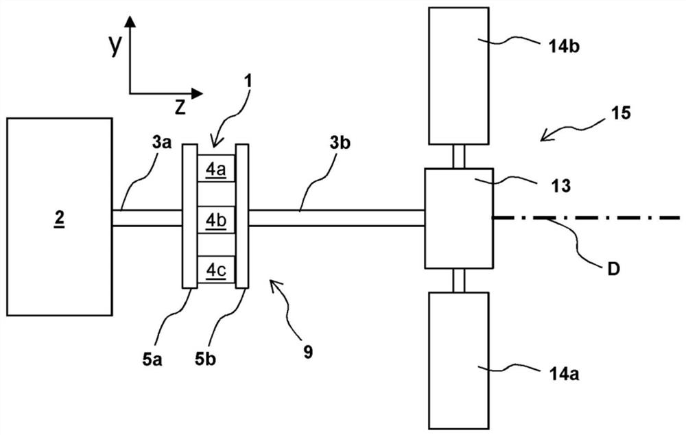
[0106] figure 1 A top view of a first exemplary embodiment of a measuring assembly 9 for determining forces and / or torques on torque-transmitting shafts 3 a , 3 b on a drive test stand 15 is shown. The shafts 3a, 3b in this case connect the motor 2, which is mainly used as a bearing device for the shafts 3a, 3b, to a transmission and a differential 13, which in turn are connected via shaft sections to the wheel gauges. The force gauges 14a, 14b are connected.

[0107] Between the first section 3 a of the shaft and the second section 3 b of the shaft is arranged a measuring system 1 which has a two-part measuring flange 5 a , 5 c as a fastening device. The first section 3a of the shaft is connected in a rotationally fixed manner to the first part 5a of the measuring flange, and the second section 3b of the shaft is connected in a rotationally fixed manner to the second part 5b of the measuring flange. The three piezoelectric elements 4 a , 4 b , 4 c are arranged between the t...


PUM


Abstract

The invention relates to a measuring system (1) for determining a force and / or a torque on a torque-transmitting shaft (3), wherein: the measuring system (1) has at least three, in particular at leastfour, piezoelectric elements (4a, 4b, 4c, 4d) each having a preferred direction (Va, Vb, Vc, Vd) and each being arranged at different positions about a rotational axis (D) of the shaft (3) in a forceflow transmitted via the shaft (3), said arrangement being such that a force of the force flow acts, in particular exclusively, on the piezoelectric elements (4a, 4b, 4c, 4d); the preferred directions each lie parallel to or in a single plane which is intersected by the rotational axis; and the preferred directions (Va; Vb; Vc; Vd) of at least two, in particular at least three, of the piezoelectric elements (4a, 4b, 4c, 4d) are oriented neither parallel nor antiparallel to one other.

Description

technical field [0001] The invention relates to a measuring system for determining a force and / or a torque on a torque-transmitting shaft, wherein the measuring system has at least three, in particular at least four piezoelectric elements, each with a preferably The piezoelectric elements are each arranged at different positions around the axis of rotation of the shaft in the force flow transmitted via the shaft in such a way that the forces of the force flow are in particular only present at the piezoelectric elements. Background technique [0002] When developing and tuning motors, especially internal combustion engines or electric motors, it is important to know the torque at the motor shaft as precisely as possible, especially in test bench operation. [0003] It is known from the prior art to use measuring systems with strain gauges or piezoelectric sensors for this purpose. [0004] Resistance strain gauges and similar measuring elements are commonly used to measure s...

Claims


Application Information

Patent Timeline
IPC IPC(8): G01L5/1627G01L3/10G01L3/14G01L5/00G01L1/16
CPCG01L3/02G01L3/108G01L3/1457G01L3/16G01L5/167G01L1/16G01L3/10G01L3/1464G01L5/0042G01L5/0019G01L5/162
Inventor 亚历山大·施瑞克弗朗茨·德雷西贝纳赫尔穆特·科卡尔马里奥·普罗斯特迈克尔·赫斯勒
Owner AVL LIST GMBH
Features
  • R&D
  • Intellectual Property
  • Life Sciences
  • Materials
  • Tech Scout
  • Unparalleled Data Quality
  • Higher Quality Content
  • 60% Fewer Hallucinations
Learn More