Method and equipment for realizing buzzing through vibration of stepping motor of printer

A technology of stepping motors and printers, applied in printing devices, motor generator control, printing, etc., can solve the problems of high implementation cost, occupying CPU port resources, etc., and achieve the effect of increasing hardware costs

Active Publication Date: 2020-11-10
福建星谷信息科技有限公司
View PDF11 Cites 0 Cited by
  • Summary
  • Abstract
  • Description
  • Claims
  • Application Information

AI Technical Summary

Problems solved by technology

Because this traditional implementation method requires a dedicated buzzer component and its corresponding drive circuit component, and requires a CPU output physical port as the output of the buzzer control signal, the implementation cost of this solution is relatively high. , while occupying the CPU port resources of the system

Method used


Image

  • Method and equipment for realizing buzzing through vibration of stepping motor of printer
  • Method and equipment for realizing buzzing through vibration of stepping motor of printer
  • Method and equipment for realizing buzzing through vibration of stepping motor of printer

Examples


Embodiment 1

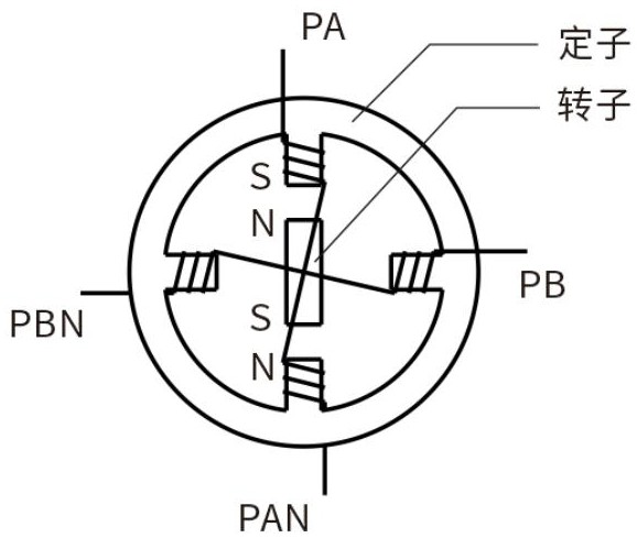
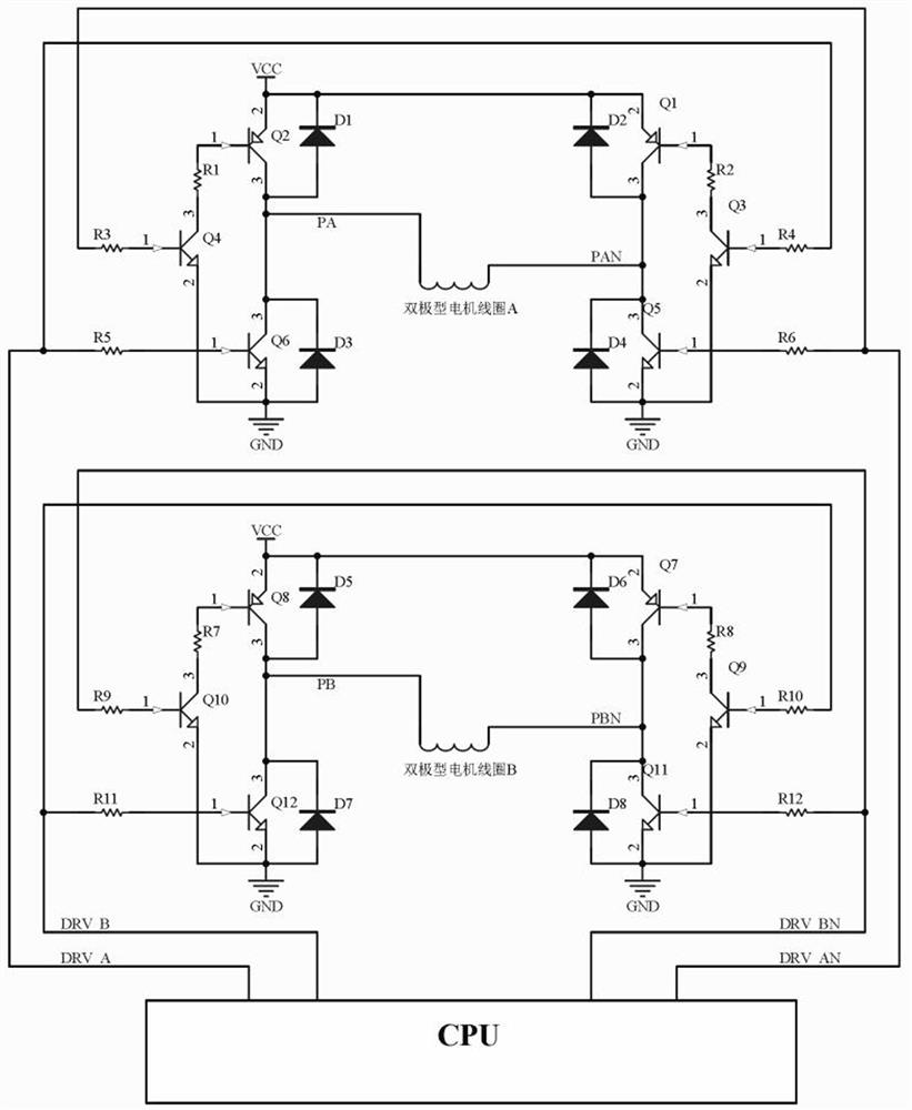
[0042] In this embodiment, a bipolar motor is taken as an example for illustration, such as figure 1 , image 3 as well as Figure 5 shown.

[0043] When the stepper motor of the printer stops running, when the CPU of the printer controller receives a buzzer prompt or warning action, the CPU starts the buzzer driver control program to execute. Drive signals DRV_A, DRV_AN, DRV_B, DRV_BN are generated by the control program on the physical ports of the CPU.

[0044] In the initial state, the driving signals DRV_A and DRV_AN are at low level, at this time, the switching tubes Q1, Q2, Q5, and Q6 of the driving circuit of the stepping motor coil A are all closed, and the coil A of the stepping motor does not pass through the excitation current; at the same time When the drive signals DRV_B and DRV_BN are at low level, the switch tubes Q7, Q8, Q11 and Q12 of the drive circuit of the coil B of the stepping motor are all turned off, and the coil B of the stepping motor has no excit...

Embodiment 2

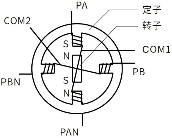
[0050] In this embodiment, the unipolar motor is taken as an example for illustration, such as figure 2 , Figure 4 as well as Figure 5 shown.

[0051] The timing sequence of the driving signal is the same as that of the first embodiment, and the realization principle is the same as that of the first embodiment, the only difference is that the corresponding difference between the driving signal and the switch of the switching tube of the driving circuit is different. Specifically include the following steps:

[0052] When the stepper motor of the printer stops running, when the CPU of the printer controller receives a buzzer prompt or warning action, the CPU starts the buzzer driver control program to execute. Drive signals DRV_A, DRV_AN, DRV_B, DRV_BN are generated by the control program on the physical ports of the CPU.

[0053] In the initial state, the driving signals DRV_A and DRV_AN are at low level. At this time, the switching tubes Q13 and Q15 of the driving circ...


PUM


Abstract

The invention relates to a method and equipment for realizing buzzing through vibration of a stepping motor of a printer. A controller of the printer inputs a pulse signal to a driving circuit of thestepping motor of the printer, so that a rotor of the stepping motor performs excitation switch vibration according to a driving frequency, and buzzing sound is generated through vibration. The hardware cost of printer parts is not increased while the buzzing function is achieved.

Description

technical field [0001] The invention relates to the technical field of printer design, in particular to a method and equipment for realizing buzzing by vibration of a stepping motor of a printer. Background technique [0002] Common printers need to provide sounds for warning or prompting, all of which use dedicated buzzer components, combined with buzzer drivers or oscillation circuits and control signals, to emit the required buzzer sound. Because this traditional implementation method requires a dedicated buzzer component and its corresponding drive circuit component, and requires a CPU output physical port as the output of the buzzer control signal, the implementation cost of this solution is relatively high. , while occupying the CPU port resources of the system. Contents of the invention [0003] In view of this, the object of the present invention is to propose a method and device for buzzing by vibration of a stepping motor of a printer, which can realize the buzz...

Claims


Application Information

Patent Timeline
IPC IPC(8): B41J29/46H02P8/12H02P8/18
CPCB41J29/46H02P8/12H02P8/18
Inventor 郑辉飞肖民杰杜俊青
Owner 福建星谷信息科技有限公司
Why Eureka
Try Eureka