In-situ cold recycled drainage anti-crack pavement structure and cold recycled pavement construction method
A pavement structure and cold regeneration technology, which is applied to drainage structures, separation methods, chemical instruments and methods, etc., can solve the problems of unreasonable design of water filter plates and vehicles being taken away, and achieve the effect of reducing labor costs and improving stability
- Summary
- Abstract
- Description
- Claims
- Application Information
AI Technical Summary
Problems solved by technology
Method used
Image
Examples
Embodiment 1
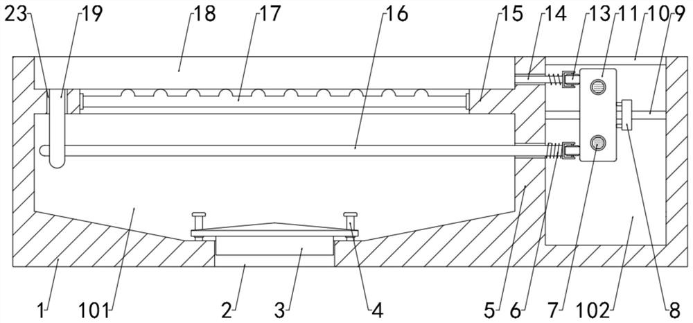
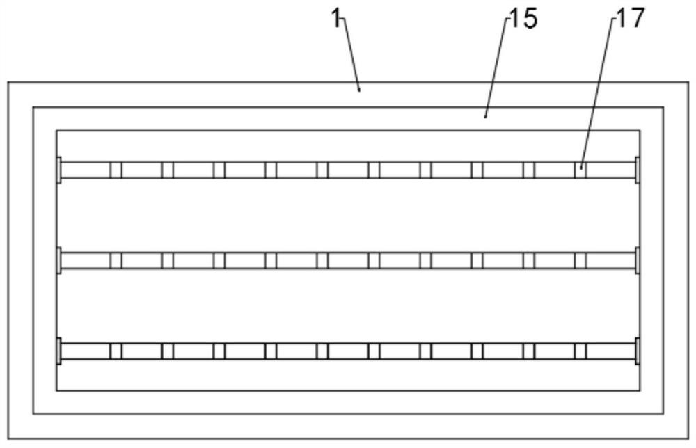
[0037] see Figure 1-6 , in-situ cold regeneration drainage anti-cracking pavement structure, including a frame body 1 with an opening at the top arranged inside the pavement structure, a partition 5 is formed on the bottom inner wall of the frame body 1, and the partition plate 5 divides the frame body 1 into chambers One 101 and chamber two 102 are two chambers, the lower surface wall of chamber one 101 has a port 2, the top of chamber two 102 is equipped with a cover 10, and the cover 10 seals chamber two 102, and the cavity The inner wall of chamber one 101 is formed with a ring-shaped bearing platform 15 and the top of the bearing platform 15 is provided with a water filter plate 18, and a plurality of support rods 17 are fixed on the inner wall of the bearing platform 15. The lower table walls are attached to each other, which improves the bending resistance of the water filter plate 18. The first limit pin 14 and the second limit pin 16 run through the partition plate 5...
Embodiment 2
[0040] see figure 1 and Figure 4 The limiter includes a threaded rod 22 arranged in the horizontal direction between two guide rods one 7, the threaded rod 22 is connected to the inner wall of the chamber two 102 through bearings, and the outside of the threaded rod 22 is screwed with a drive block 8. During the rotation of the threaded rod 22, the drive block 8 moves in the horizontal direction, the drive block 8 runs through the guide rod 2 9, the guide rod 2 9 is fixedly connected with the inner wall of the chamber 2 102, and the guide rod 2 9 runs through Open the avoidance groove 21 on the slide block 11, the avoidance groove 21 is slidingly matched with the guide rod 2 9, and the end of the drive block 8 near the slide block 11 is equipped with a roller 2 27, and the roller 2 27 avoids the drive block 8 and the slide block 11. friction between.
[0041] The difference from Example 1 is that
Embodiment 3
[0043] see figure 1 and Figure 5 , the port 2 is provided with a pressure plate 3, and the bottom inner wall of the pressure chamber 101 is fixed with a column 4, and the column 4 runs through the through hole 24 provided on the pressure plate 3, and the ball 12 is installed on the inner wall of the through hole 24, under normal conditions , the pressure plate 3 is attached to the bottom cavity wall of the chamber one 101 and seals the port 2, which can avoid the overflow of the odor and play a deodorizing effect. When there is water in the chamber one 101, the pressure plate 3 Under the action of buoyancy, the upward movement can facilitate the discharge of accumulated water. At the same time, the top of the pressure plate 3 is set in a conical shape, which can prevent heavy objects from accumulating on the top of the pressure plate 3. The ball 12 avoids the gap between the column 4 and the wall of the through hole 24. The friction between them makes the movement of the pre...
PUM
 Abstract
Description
Claims
Application Information
 - R&D
- Intellectual Property
- Life Sciences
- Materials
- Tech Scout
- Unparalleled Data Quality
- Higher Quality Content
- 60% Fewer Hallucinations
Browse by: Latest US Patents, China's latest patents, Technical Efficacy Thesaurus, Application Domain, Technology Topic, Popular Technical Reports.
© 2025 PatSnap. All rights reserved.Legal|Privacy policy|Modern Slavery Act Transparency Statement|Sitemap|About US| Contact US: help@patsnap.com


