
A 3D printed prefabricated reinforced concrete component and its manufacturing method

A technology of reinforced concrete and 3D printing, applied in building components, building structures, walls, etc., can solve the problems of not giving full play to the advantages of 3D printing, difficult calculation analysis and engineering applications, and low automation of reinforcement layout, saving Cost of material and labor consumption, avoidance of body shape constraints, the effect of high degree of freedom in body shape design

Active Publication Date: 2022-03-15
SOUTH CHINA UNIV OF TECH +2
View PDF9 Cites 0 Cited by
  • Summary
  • Abstract
  • Description
  • Claims
  • Application Information

AI Technical Summary

Problems solved by technology

[0004] Due to the special construction process of 3D printing concrete layer by layer, it is difficult to use traditional methods for steel reinforcement construction. Recently, researchers have used composite fibers or fine steel wires to reinforce concrete members, but this method is different from traditional reinforcement methods. It is difficult to carry out calculation analysis and engineering application according to the current method and engineering experience; another construction method is to print the hollow concrete shell first, and then put the steel cage which has been bound or welded in advance, and then pour the concrete and Vibration, this method essentially just eliminates the work of setting up the formwork, the degree of automation in the laying of steel bars is low, and the advantages of 3D printing are not fully utilized

Method used


Image

  • A 3D printed prefabricated reinforced concrete component and its manufacturing method
  • A 3D printed prefabricated reinforced concrete component and its manufacturing method
  • A 3D printed prefabricated reinforced concrete component and its manufacturing method

Examples


Embodiment 1

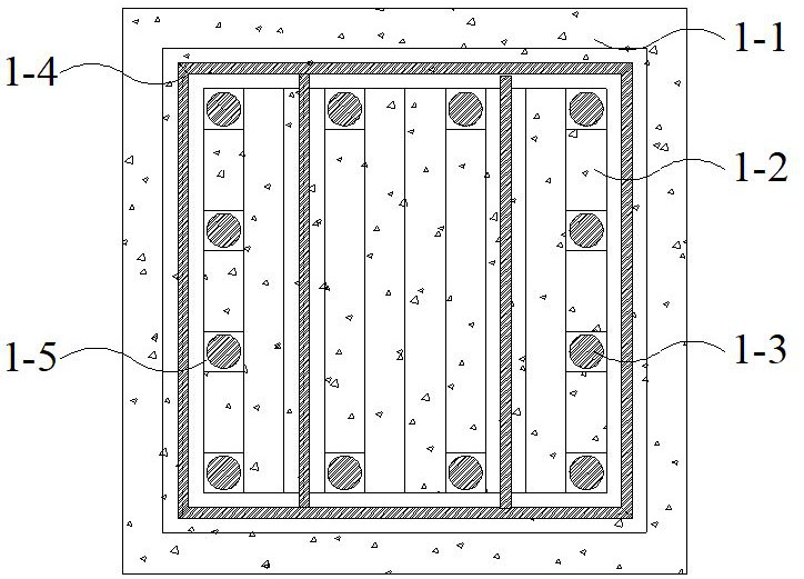
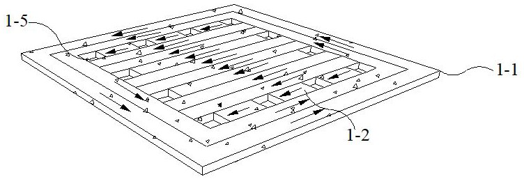
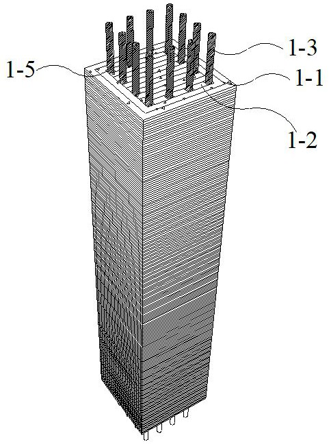
[0052] Such as Figure 1 ~ Figure 4 As shown, a 3D printed prefabricated reinforced concrete rectangular column, including: rectangular column 3D printed shell 1-1, rectangular column 3D printed internal structure 1-2, rectangular column stirrup 1-4, rectangular column longitudinally reserved Holes 1-5 and rectangular column longitudinal ribs 1-3; the rectangular column 3D printed shell 1-1 is printed around the component axis according to the shape of the component; the rectangular column 3D printed internal structure 1-2 is printed on the rectangular column 3D printed shell 1 -1, if figure 1 As shown; the stirrups are directly placed on the shell part of the printed concrete in the direction parallel to the printing plane at every fixed number of printing layers, and the longitudinal reserved holes are located in the internal structure of the concrete member; In the reserved holes, the grouting material is poured into the holes in the later stage to realize the fixation of ...

Embodiment 2

[0062] Such as Figure 5 ~ Figure 8 As shown, a 3D printed prefabricated reinforced concrete box girder, including: box girder 3D printed shell 2-1, box girder 3D printed internal structure 2-2, box girder longitudinally reserved holes 2-6 , box girder longitudinal reinforcement 2-4, box girder waist reinforcement 2-3 and box girder stirrup 2-5; the box girder 3D printing shell 2-1 is printed around the component axis according to the component shape; The box girder 3D printing internal structure 2-2 is printed in the box girder 3D printing shell 2-1, such as Figure 5 As shown; the longitudinally reserved hole 2-6 of the box girder is located in the internal structure of the concrete member; the longitudinal stress rib 2-4 of the box girder is directly penetrated in the longitudinally reserved hole 2-6 of the box girder, and in the later stage The grouting material is poured into the hole to realize the fixing of the longitudinal reinforcement 2-4 of the box girder; the stir...

Embodiment 3

[0075] like Figure 9 ~ Figure 12 As shown, a prefabricated 3D printed reinforced concrete rectangular column with variable cross-section includes: 3D printed outer shell 3-1 of variable cross-section rectangular column, 3D printed internal structure 3-2 of variable cross-section rectangular column, longitudinal reservation of variable cross-section rectangular column Holes 3-5, variable cross-section rectangular column longitudinal reinforcement 3-3 and variable cross-section rectangular column stirrup 3-4; the variable cross-section rectangular column 3D printing shell 3-1 is printed around the component axis according to the shape of the component; the variable cross-section rectangular The column 3D printing internal structure 3-2 structure is printed in the variable cross-section rectangular column 3D printing shell 3-1, such as Figure 9 As shown; the longitudinal reserved holes 3-5 of the variable cross-section rectangular column are located in the internal structure of...


PUM


Abstract

A 3D printed prefabricated reinforced concrete component and a manufacturing method thereof. Components include: 3D printed concrete shell, 3D printed concrete component internal structure, longitudinal reserved holes, longitudinal steel bars and stirrups; 3D printed concrete shell is printed around the component axis according to the component shape; 3D printed concrete component internal structure is printed on Inside the shell; the longitudinal reserved holes are located in the internal structure of the concrete member; the longitudinal steel bars are penetrated into the reserved holes, and the grouting material is poured into the holes to fix the longitudinal bars; The orientation concentric is placed directly on the shell part of the printed concrete. The 3D printed concrete components do not need to use templates, and can produce component forms that are difficult to achieve in traditional construction, which can improve the design freedom of components; the reinforcement mode of the 3D printed concrete components is similar to that of traditional reinforced concrete components, and traditional theories can be used Design, and easy to make.

Description

technical field [0001] The invention relates to the technical field of concrete 3D printing in construction engineering, in particular to a 3D printed assembled reinforced concrete component and a manufacturing method thereof. Background technique [0002] Compared with the traditional concrete cast-in-place construction technology, concrete 3D printing technology has the following advantages: (1) No need to use concrete formwork and its supports during the construction process, and no need to vibrate the concrete after printing, which reduces the consumption of materials and labor; (2) The construction speed is fast and the construction time is short; (3) through highly accurate design and printing, the possibility of construction errors is reduced; (4) the degree of construction automation is high, which can improve the construction environment and reduce labor consumption; Component shapes are limited, and components with different shapes can be printed, thus improving th...

Claims


Application Information

Patent Timeline
Patent Type & Authority Patents(China)
IPC IPC(8): E04B1/20E04B2/00B33Y80/00B33Y10/00
CPCE04B1/20E04B2/00B33Y80/00B33Y10/00B28B1/001B28B23/02E04G21/04E04B1/04E04C3/20
Inventor 甘振先张海燕成尚锋卜继斌
Owner SOUTH CHINA UNIV OF TECH
Learn More