A high-power laser beam far-field combination focal spot measurement method and system

A measurement method and measurement system technology, applied in the field of focal spot measurement, can solve problems such as deviation of physical experiment results, and achieve the effects of avoiding differences, reducing differences, and avoiding measurement distortion.

Active Publication Date: 2021-07-27
XI'AN INST OF OPTICS & FINE MECHANICS - CHINESE ACAD OF SCI
View PDF5 Cites 0 Cited by
  • Summary
  • Abstract
  • Description
  • Claims
  • Application Information

AI Technical Summary

Problems solved by technology

[0004] The present invention aims to solve the technical problem in the prior art that there is a deviation in the physical experiment results due to the difference between the morphology of the focal spot of the cluster terminal and the focal spot of the single beam terminal, and provides a high-power laser beam remote Field combination focal spot measurement method and system

Method used


Image

  • A high-power laser beam far-field combination focal spot measurement method and system
  • A high-power laser beam far-field combination focal spot measurement method and system
  • A high-power laser beam far-field combination focal spot measurement method and system

Examples


Embodiment Construction

[0048] In order to make the purpose, advantages and features of the present invention more clear, a high-power laser beam far-field combination focal spot measurement method and system proposed by the present invention will be further described in detail below in conjunction with the accompanying drawings and specific embodiments. The advantages and features of the present invention will be more clear from the following specific embodiments. It should be noted that: the drawings are all in a very simplified form and use inaccurate proportions, which are only used to facilitate and clearly illustrate the purpose of the embodiment of the present invention; secondly, the structures shown in the drawings are often actual structures part.

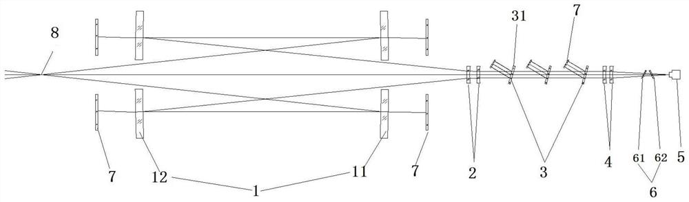
[0049] The present invention is a high-power laser beam far-field combination focal spot measurement system, such as figure 1 As shown, it includes a sampling mirror group 1, a collimating negative lens group 2, a first attenuating mirror group...


PUM


Abstract

The invention discloses a method and system for measuring the focal spot of a high-power laser cluster far-field combination. technical problem. The measurement system of the present invention includes a sampling mirror group, a collimating negative lens group, a first attenuation mirror group, a magnifying mirror group and a CCD which are sequentially arranged along the optical path; Sampling mirror Ⅱ and sampling mirror Ⅰ respectively equipped with light holes; both sampling mirror Ⅱ and sampling mirror Ⅰ are parabolic mirrors, and the concave surfaces of the two are opposite; the collimating negative lens group is used to collimate the sampled beam Carry out beam reduction and collimation; the first attenuation lens group contains at least two attenuation sheets, and the angle between the normal of each attenuation sheet and the beam is θ, 10°<θ<20°; the magnifying lens group is used to adjust the attenuation The beam after amplification is enlarged; CCD is used to acquire the image of the beam after amplification.

Description

technical field [0001] The invention relates to a focal spot measurement method and system, in particular to a high-power laser beam far-field combined focal spot measurement method and system. Background technique [0002] The NIF (National Ignition Facility Project) laser device contains 192 laser beams. These 192 laser beams are distributed on a sphere, and the parallel incident laser light is converged to the center of the sphere through the terminal optical assembly mounted on the sphere. In order to save the space of the sphere, the NIF laser device designs the terminal optical components as a cluster terminal with a total of 4 beams arranged in the form of 2×2. Each cluster terminal is taken as a whole. Since the optical components in the cluster terminal are independent of each other, the beam It also spreads independently in space. After the beam gathering terminal converges the beam to the center of the sphere, the spot at the center of the sphere is the combined ...

Claims


Application Information

Patent Timeline
Patent Type & Authority Patents(China)
IPC IPC(8): G01B11/24G01M11/02
CPCG01B11/24G01M11/02G01M11/0257
Inventor 李红光达争尚袁索超陈永权董晓娜
Owner XI'AN INST OF OPTICS & FINE MECHANICS - CHINESE ACAD OF SCI
Why Eureka
Try Eureka