
Battery peak power prediction method and device

A technology of peak power and prediction method, applied in measurement devices, battery/fuel cell control devices, secondary batteries, etc., can solve the problems of battery attenuation, SOC constraints, battery overcharge and overdischarge, etc., to prevent overcharge effect of overdischarge

Active Publication Date: 2020-11-10
SAIC MOTOR
View PDF9 Cites 0 Cited by
  • Summary
  • Abstract
  • Description
  • Claims
  • Application Information

AI Technical Summary

Problems solved by technology

Among them, although the off-line table method explains the principle of power prediction well, the model of this method is too simple, only considering the factor of voltage, and does not consider the constraint of SOC, which will cause the predicted power to be larger than the real value, and the battery Overcharging and overdischarging may occur, which may easily lead to safety problems and affect the life of the battery pack.
Moreover, the experimental workload of this method is relatively large. In order to complete the above-mentioned charging and discharging power meter, a large number of tests are required, and it is especially difficult to complete the tests under different life states.
In addition, the tables of this method are obtained from offline tests, so the adaptability to online applications is relatively poor, and it does not consider battery temperature changes, battery attenuation, etc.
[0004] However, the method of predicting battery SOP based on the dynamic electrochemical model of the battery does not dynamically identify the parameters of the battery model. Under continuous sampling periods, the formula needs to introduce integral calculations, which will become very complicated and greatly increase the amount of calculation.

Method used


Image

  • Battery peak power prediction method and device
  • Battery peak power prediction method and device
  • Battery peak power prediction method and device

Examples


Embodiment Construction

[0058] In order to make the above objects, features and advantages of the present application more obvious and understandable, the embodiments of the present application will be further described in detail below in conjunction with the accompanying drawings and specific implementation methods.

[0059] In order to facilitate the understanding of the technical solution provided by the present application, a brief description of the research background of the technical solution of the present application is given below.

[0060] As we all know, energy saving, environmental protection and safety are the development direction of future automobiles. With the rapid development of economy and the improvement of people's awareness of environmental protection, the utilization rate of electric vehicles is getting higher and higher, and the estimation of SOC and SOP of power batteries is the One of the key technologies, accurate prediction of the peak power of the power battery is an impo...


PUM


Abstract

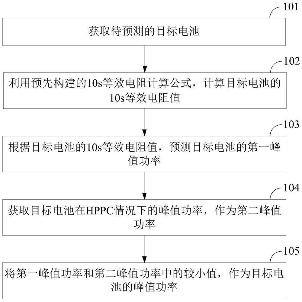
The invention discloses a battery peak power prediction method and device, and the method comprises the steps: obtaining a to-be-detected target battery, calculating a 10s equivalent resistance valueof the target battery through a pre-built 10s equivalent resistance calculation formula, predicting the first peak power of the target battery according to the 10s equivalent resistance value, obtaining the peak power of the target battery under the HPPC condition as the second peak power, and then taking the smaller value of the first peak power and the second peak power can serve as the peak power of the target battery. Therefore, the 10s peak power of the target battery is predicted on the basis of a pre-constructed 10s equivalent resistance calculation formula, and the prediction accuracyof the 10s peak power of the target battery is improved; the prediction result is compared with the peak power of the target battery under the HPPC condition to obtain the final 10s peak power of thetarget battery, so that the overcharge and overdischarge phenomenon of the target battery can be prevented, and the target battery can be better protected.

Description

technical field [0001] The present application relates to the technical field of batteries, in particular to a method and device for predicting battery peak power. Background technique [0002] With the rapid development of the economy, the utilization rate of electric vehicles is getting higher and higher. As the power source or auxiliary power source of electric vehicles, the development of power batteries is particularly important. The prediction of the peak power (State of Power, referred to as SOP) of the power battery is also one of the key technologies for electric vehicles. Among them, power battery power includes discharge power and charging power. Generally, the maximum discharge power and maximum charging power are defined when the battery does not exceed the battery voltage, state of charge (SOC for short) and current limit within a period of time. is the peak power of the battery. [0003] The current methods for battery SOP prediction are generally divided in...

Claims


Application Information

Patent Timeline
Patent Type & Authority Applications(China)
IPC IPC(8): G01R31/367G01R31/396G06F17/10B60L58/10
CPCG01R31/367G01R31/396G06F17/10B60L58/10H01M10/48G01R31/3647Y02E60/10Y02T10/70
Inventor 石泉颜晨星张志运王倩倩井岩丁笑张旺程凯商丹
Owner SAIC MOTOR
Learn More