Unlock instant, AI-driven research and patent intelligence for your innovation.
A pole piece winding method and rolled pole piece
What is Al technical title?
Al technical title is built by PatSnap Al team. It summarizes the technical point description of the patent document.
A pole piece and rolling technology is applied to the field of pole piece winding method and rolled pole piece.
Active Publication Date: 2022-01-04
JIANGSU ZENIO NEW ENERGY BATTERY TECH CO LTD
View PDF6 Cites 0 Cited by
Summary
Abstract
Description
Claims
Application Information
AI Technical Summary
This helps you quickly interpret patents by identifying the three key elements:
Problems solved by technology
Method used
Benefits of technology
Problems solved by technology
Although the above solution has improved the problem of tab folding to a certain extent, due to the existence of the coating area of the pole piece, there is a certain distance between the notch and the coating edge, which reduces the effect of the notch and cannot prevent the tab from being rolled during the winding process. fold in
Method used
Image
Click on the blue label to locate the original text in one second.
Reading with bidirectional positioning of images and text.
Examples
Embodiment 1
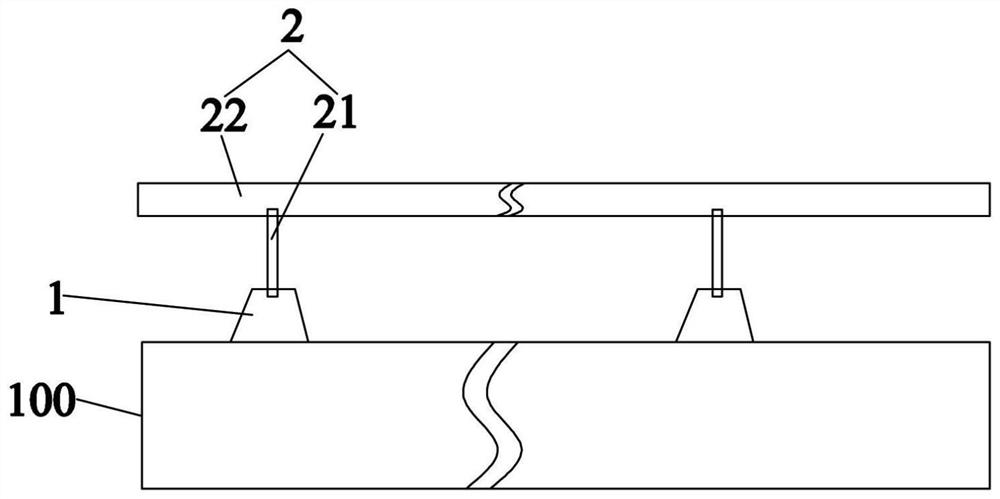
[0047] refer to Figure 1~3 , the present embodiment provides a pole piece winding method, comprising the following steps:
[0048] Coating a thin current collector with a thickness of 20 μm to form a pole piece 100 with a coated area and a non-coated area, after rolling the pole piece 100, die-cut a plurality of trapezoidal tabs 1 on the non-coated area, The height of the tab 1 is 0.1-30cm;
[0049] Connect the anti-folding part 2 on the tab 1, the anti-folding part 2 includes a connecting part 21 and a supporting part 22 connected to each other, the connecting part 21 is connected with the tab 1, and the supporting part 22 is arranged side by side with the pole piece 100; the connecting part 21 is a cylindrical strip, the diameter of the connecting part 21 is 0.05mm~30cm, and the length is 0.5~30cm; the material of the connecting part 21 is PET; the supporting part 22 is a rectangular strip, the width of the supporting part 22 is 0.5~50cm, and the thickness The material of t...
Embodiment 2
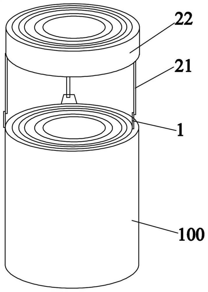
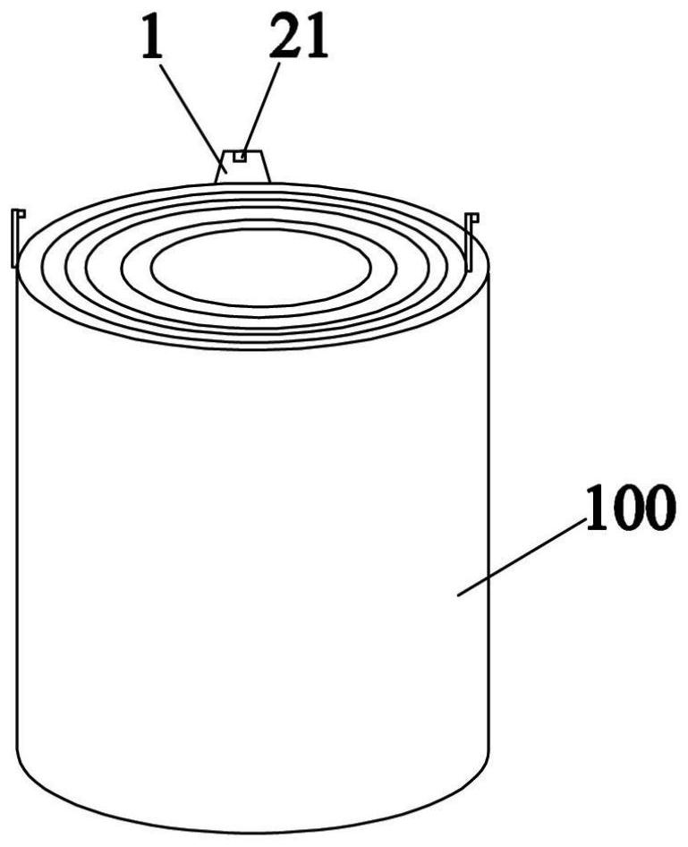
[0052] refer to Figure 4~6 , the difference between this embodiment and embodiment 1 is:
[0053] A plurality of rectangular tabs 1 are die-cut in the non-coating area.
[0054] The connection part 21 is in the shape of a long and narrow strip, and the width of the connection part 21 is 0.05mm-30cm, and the length is 0.5-30cm. Both the connecting portion 21 and the supporting portion 22 are made of aluminum. The connecting part 21 and the supporting part 22 are integrally formed. The end of the connecting portion 21 is connected to the tab 1 by means of adhesion, electric welding or thermal fusion.
[0055] When the pole piece 100 is rolled up to the position close to the tab 1 , it is cut along the end of the connecting portion 21 , and part of the tab 1 is cut off at the same time, so as to disconnect the tab 1 from the anti-folding member 2 .
[0056] The rest are the same as in Embodiment 1, and will not be repeated here.
PUM
Property
Measurement
Unit
diameter
aaaaa
aaaaa
length
aaaaa
aaaaa
width
aaaaa
aaaaa
Abstract
The invention belongs to the technical field of battery production, and in particular relates to a pole piece winding method, comprising the following steps: coating a thin current collector to form a pole piece with a coated area and a non-coated area, and rolling the pole piece Finally, the tab is die-cut on the non-coating area; the anti-folding member is connected to the tab, and the anti-folding member includes a connecting part and a supporting part connected to each other, and the connecting part and the The pole lug is connected, the support part and the pole piece are arranged side by side; the pole piece is rolled up, and the anti-folding member is also rolled up at the same time, when the pole piece is rolled up to the pole piece At the ear position, disconnect the connection between the tab and the anti-folding member, continue to roll, and finally obtain the rolled pole piece and the rolled-up anti-folding member. In addition, the invention also relates to a rolled pole piece. Compared with the prior art, the present invention can effectively prevent the tab from being folded during the coiling stage of the pole piece.
Description
technical field [0001] The invention belongs to the technical field of battery production, and in particular relates to a pole piece winding method and a rolled pole piece. Background technique [0002] Lithium-ion batteries have been receiving great attention in consumer electronics and power products due to their high operating voltage, high energy density, long cycle life, safety and environmental protection. At present, lithium-ion batteries in the field of new energy are developing rapidly, followed by an increasing demand for lithium-ion batteries with high specific energy density. [0003] With the improvement of power battery energy density requirements, thin current collectors are more widely used in the production of lithium battery electrodes. For current collectors with a thickness below 20 microns. [0004] In the existing technology, the tension of the tab is generally changed by applying notches to the tab. Specifically, the utility model patent with the au...
Claims
Application Information
Patent Timeline
Application Date:The date an application was filed.
Publication Date:The date a patent or application was officially published.
First Publication Date:The earliest publication date of a patent with the same application number.
Issue Date:Publication date of the patent grant document.
PCT Entry Date:The Entry date of PCT National Phase.
Estimated Expiry Date:The statutory expiry date of a patent right according to the Patent Law, and it is the longest term of protection that the patent right can achieve without the termination of the patent right due to other reasons(Term extension factor has been taken into account ).
Invalid Date:Actual expiry date is based on effective date or publication date of legal transaction data of invalid patent.
