Dual-mode dielectric waveguide filter

A dielectric waveguide and filter technology, applied in the field of dual-mode dielectric waveguide filters, can solve the problems of large thickness of dielectric block, large dual-mode cavity, inflexible size design, etc., achieving good tuning effect and direct sensitivity to the influence of electromagnetic field. Effect

Pending Publication Date: 2020-11-10
SOUTH CHINA UNIV OF TECH
View PDF0 Cites 5 Cited by
  • Summary
  • Abstract
  • Description
  • Claims
  • Application Information

AI Technical Summary

Problems solved by technology

[0003] Published articles or patents mostly involve single-mode dielectric waveguide filters. Most of the resonators use single blind holes, and a few use two to three blind holes. However, regardless of the number of blind holes, this type of filter Only one mode is used in each cavity of the device, the space utilization rate of the cavity can continue to be improved, and there is the possibility of further miniaturization
[0004] There are two main forms of existing dual-mode and multi-mode technologies. The first is to use the inherent modes of the waveguide cavity to couple through chamfered corners. The size design of this method is not flexible, and the thickness of the dielectric block is too large, which is not conducive to Base station height reduction
The second is to control the dual-mode by punching a blind hole with different radii on the upper and lower surfaces. The dual-mode cavity required by this method is still very large, and the applied modes are the second and third modes, not the main mode. Potential for spurious passbands at low frequencies

Method used


Image

  • Dual-mode dielectric waveguide filter
  • Dual-mode dielectric waveguide filter
  • Dual-mode dielectric waveguide filter

Examples


Embodiment 1

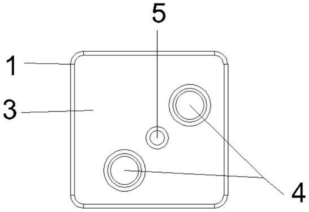
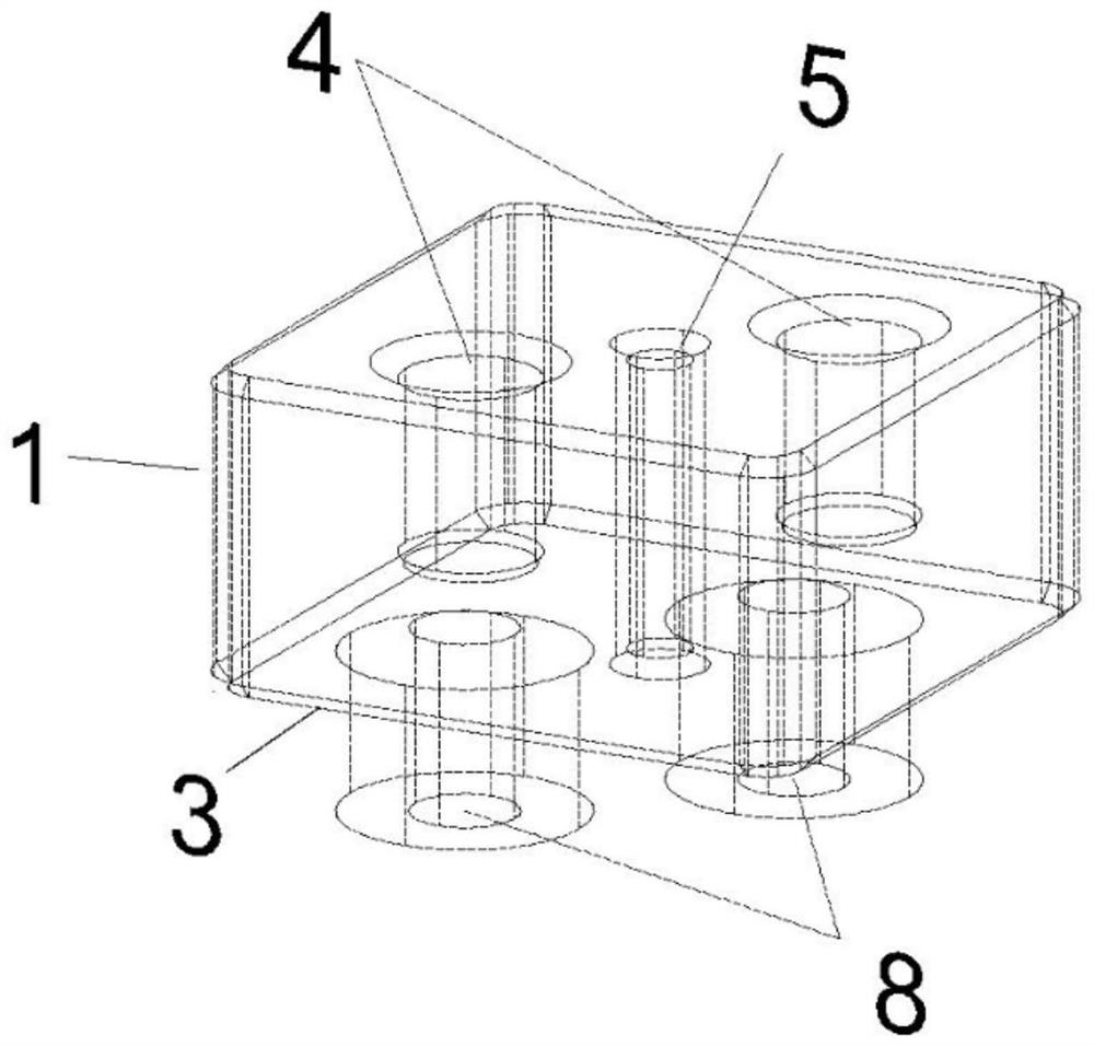
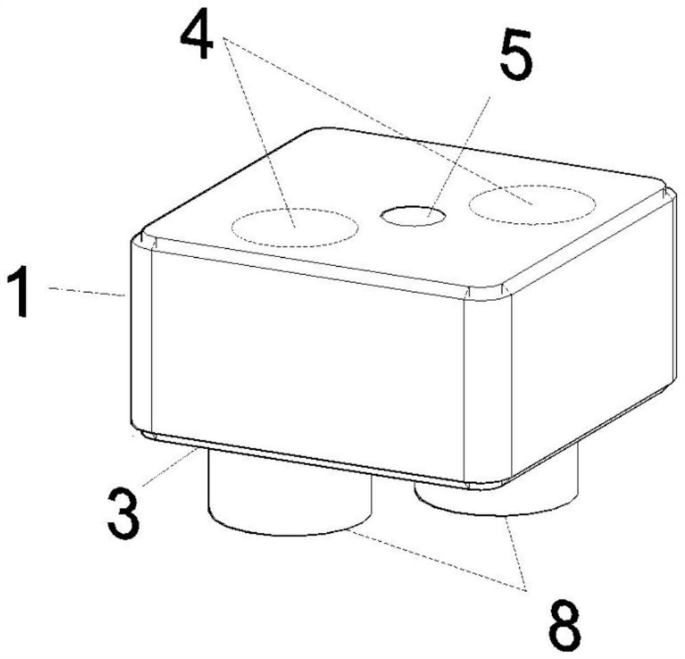
[0028] Such as Figure 1 to Figure 3 As shown, this embodiment provides a single-cavity dual-mode dielectric waveguide filter, including a silver-plated ceramic dielectric body 1 (in a rectangular shape), the bottom of the dielectric body 1 is connected to a coaxial connector 8, and the coaxial connection The filter 8 is used as the input and output port to feed the filter, and the embedded depth of the coaxial inner conductor determines the external quality factor of the input and output port, and determines the electromagnetic field energy entering the filter. The entire dielectric body 1 is formed with only one resonant cavity 3, and a dual-mode structure is arranged on the top of the resonant cavity 3. The dual-mode structure includes two tuning blind holes 4 and a coupling through slot 5 for adjusting coupling. The two tuning blind holes 4 must be driven in from the same side of the dielectric body 1, and the coupling through groove 5 is opened on the perpendicular line o...

Embodiment 2

[0033] Such as Figure 7 to Figure 9As shown, this embodiment provides a six-cavity, seven-order dual-mode dielectric waveguide filter, including a silver-plated ceramic dielectric body 1 (in a rectangular shape), the lower end of the dielectric body 1 is connected to a coaxial connector 8, and the dielectric body On 1, six resonant cavities 3 are separated by the "T"-shaped isolation through groove 2 and coupling through groove 5 that penetrate the dielectric body 1, and they are resonant cavity 31, resonant cavity 32, resonant cavity 33, resonant cavity 34, Resonant cavity 35, resonant cavity 36. The resonant cavity 35 is provided with two tuning blind holes 4, and a coupling slot 5 for adjusting the coupling is provided on the vertical line connecting the centers of the two tuning blind holes 4. A single tuning blind hole 6 for the resonant frequency of the main mode of the cavity, where the four resonators on the left form a quadrupole, and these four resonators adjust th...


PUM


Abstract

The invention discloses a dual-mode dielectric waveguide filter, and the filter comprises a dielectric body with a conductive coating on the surface, wherein the dielectric body is divided into a plurality of resonant cavities, the top of at least one resonant cavity is provided with a dual-mode structure, and the dual-mode structure comprises two tuning blind holes and a coupling through groove.The two tuning blind holes must be punched from the same side of the dielectric body, the coupling through groove is located on the perpendicular bisector of the connecting line of the circle centersof the two tuning blind holes, the two blind holes generate a pair of TM210 odd and even modes, the resonant frequency of the two blind holes is controlled by the depths of the tuning blind holes, andthe capacitance loading effect of the resonant cavity is enhanced through the two blind holes; the resonant frequency of the TM210 odd mode and the TM210 even mode is reduced, the TM210 odd mode andthe TM210 even mode become a main mode of a resonant cavity, the coupling through groove generates an inductance effect, magnetic coupling is introduced between the TM210 odd mode and the TM210 even mode, and electromagnetic coupling resonance is formed together with the two tuning blind holes. According to the invention, two modes are used in one cavity, so miniaturization of the resonant cavityand even the filter is realized.

Description

technical field [0001] The invention relates to the technical field of radio frequency and microwave filters, in particular to a dual-mode dielectric waveguide filter. Background technique [0002] The Internet of Things and the Internet of Vehicles have put forward high-speed and low-latency requirements for the 5G communication system, so the communication frequency of 5G is developed to a higher frequency band. The increase in the carrier frequency makes the transmission distance of 5G smaller, and the base stations required to be deployed are greatly The increase will cause shortage of public space resources, so filters with small size, light weight, strong selectivity, and low in-band insertion loss have become one of the urgently needed devices. [0003] Published articles or patents mostly involve single-mode dielectric waveguide filters. Most of the resonators use single blind holes, and a few use two to three blind holes. However, regardless of the number of blind h...

Claims


Application Information

Patent Timeline
Patent Type & Authority Applications(China)
IPC IPC(8): H01P1/20H01P1/208
CPCH01P1/2002H01P1/208
Inventor 褚庆昕麦健业舒佩文
Owner SOUTH CHINA UNIV OF TECH
Why Eureka
Try Eureka