Check patentability & draft patents in minutes with Patsnap Eureka AI!

Heat sink

A radiator and heat sink technology, applied in indirect heat exchangers, lighting and heating equipment, cooling/ventilation/heating renovation, etc., can solve problems such as increased thermal resistance, insufficient heating, and heat transfer without heat pipe group , to achieve uniform heat input, excellent reflow characteristics, and improve heat dissipation efficiency.

Active Publication Date: 2020-11-10
FURUKAWA ELECTRIC CO LTD
View PDF4 Cites 0 Cited by
  • Summary
  • Abstract
  • Description
  • Claims
  • Application Information

AI Technical Summary

Problems solved by technology

That is, in the heat pipe type radiator, there is room for improvement in terms of space saving of the radiator and improvement of cooling performance
[0006] In addition, there is a chamfer on the outer peripheral surface of each heat pipe, and the gap generated outside the chamfer does not help the heat transfer of the heat pipe group, so the volume of the heat receiving part, heat insulation part and heat dissipation part of the heat pipe group cannot be made large enough, There are still cases where sufficient cooling performance cannot be obtained
[0007] Furthermore, if a heat pipe group composed of a plurality of heat pipes is thermally connected to a heat generating body, the amount of heat received by the heat pipes varies according to the distance from the heat generating body.
Therefore, the heat input to the heat receiving part of the heat pipe group cannot be sufficiently uniformed, and since the thermal resistance between the heat receiving part of the heat pipe group and the heat generating body increases, there is a problem that a sufficient improvement in cooling performance cannot be achieved.

Method used


Image

  • Heat sink
  • Heat sink
  • Heat sink

Examples


Embodiment Construction

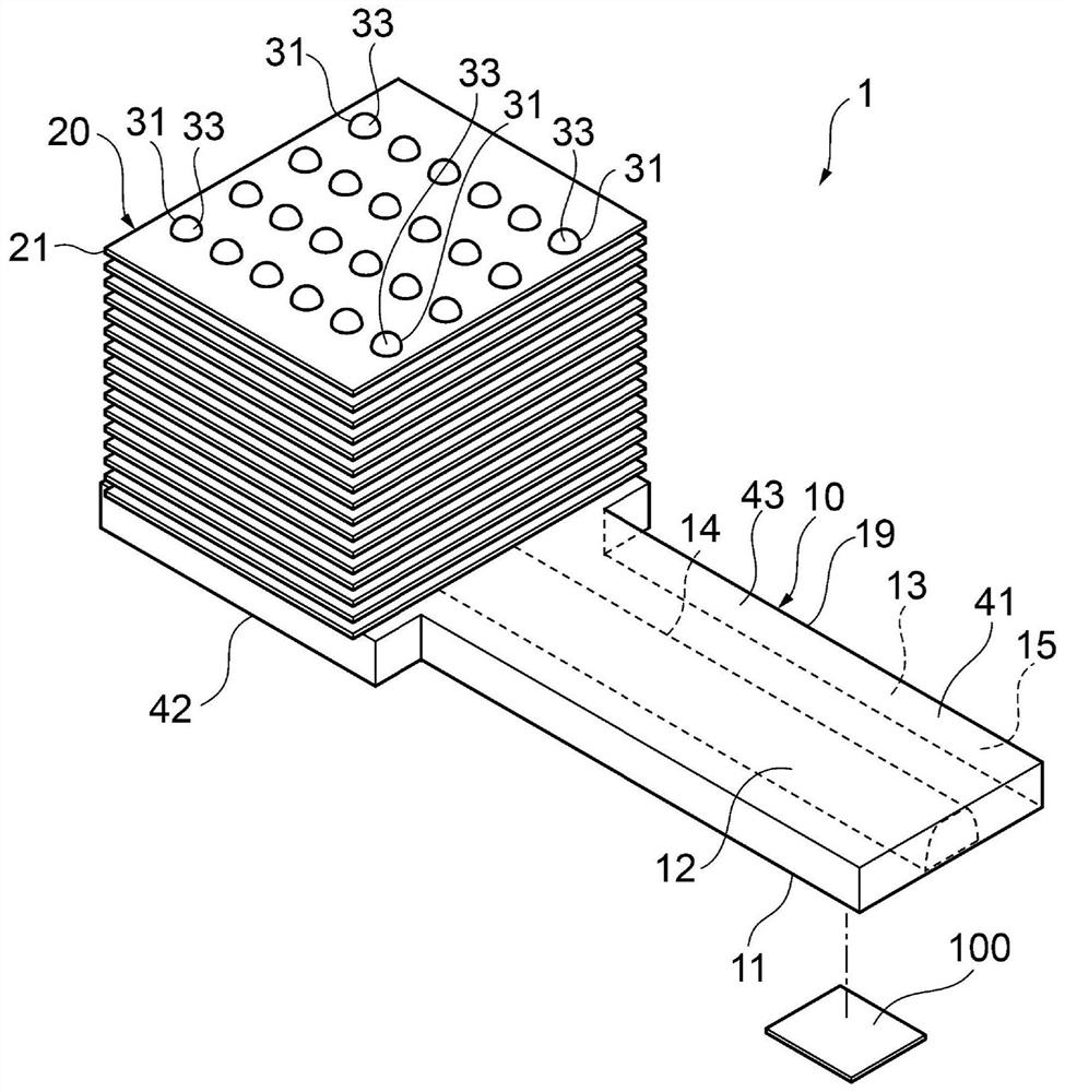
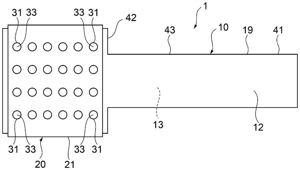
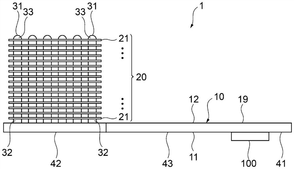
[0042] Hereinafter, a heat sink according to an embodiment of the present invention will be described with reference to the drawings. First, a heat sink according to a first embodiment of the present invention will be described. figure 1 It is a perspective view explaining the outline of the radiator of 1st Embodiment of this invention. figure 2 It is a plan view explaining the outline of the radiator of the first embodiment of the present invention. image 3 It is a side view explaining the outline of the radiator of 1st Embodiment of this invention. Figure 4 It is an explanatory diagram of a schematic plan view of the capillary structure of the heat sink according to the first embodiment of the present invention.

[0043] Such as Figure 1 ~ Figure 3 As shown, the radiator 1 of the first embodiment of the present invention includes: a heat transfer member 10 having a heat receiving portion 41 thermally connected to the heating element 100 , a heat sink group 20 thermall...


PUM


Abstract

The present invention provides a heat sink capable of having improved heat radiation efficiency from heat radiation fins and making the heat input at a heat receiving part uniform while ensuring thatthe heat receiving part, a heat insulating part, and a heat radiating part have large enough volumes even in an environment in which the installation space for the heat sink, and in particular, the widthwise installation space for the heat sink, is limited. The heat sink is provided with: a heat transport member having a heat receiving part which is thermally connected to a heat-emitting element;and a heat radiating fin group which comprises a plurality of heat radiating fins thermally connected at a heat radiating part of the heat transport member. The heat transport member has a unitary internal space communicating from the heat receiving part to the heat radiation part and having working fluid sealed therein. The cross-sectional area of the internal space of the heat radiating part ina direction which is perpendicular to the heat transport direction of the heat transport member is greater than the cross-sectional area of a heat insulating part between the heat receiving part and the heat radiating part.

Description

technical field [0001] The present invention relates to a heat sink for cooling heating elements such as electric / electronic components. Background technique [0002] As electronic devices become more functional, heating elements such as electronic components are included inside electronic devices, and many components are mounted at high density. In addition, as electronic devices become more functional, the amount of heat generated by heating elements such as electronic components increases. A heat sink may be used as a mechanism for cooling a heat generating body such as an electronic component inside an electronic device. As the heat sink, generally, a heat pipe type heat sink including a tubular heat pipe is used. [0003] As a conventional heat pipe heat sink, for example, there is a heat pipe type heat sink in which a plurality of flat fins protrude from an outer peripheral surface provided with a plurality of tubular heat pipes (Patent Document 1). The heat pipe ra...

Claims


Application Information

Patent Timeline
IPC IPC(8): H05K7/20
CPCH05K7/2029H05K7/2039H01L23/427H01L23/3672F28D15/0275F28D15/046H05K7/20336
Inventor 渡边阳介川畑贤也稻垣义胜三浦达朗青谷和明中村敏明
Owner FURUKAWA ELECTRIC CO LTD
Features
  • R&D
  • Intellectual Property
  • Life Sciences
  • Materials
  • Tech Scout
  • Unparalleled Data Quality
  • Higher Quality Content
  • 60% Fewer Hallucinations
Learn More